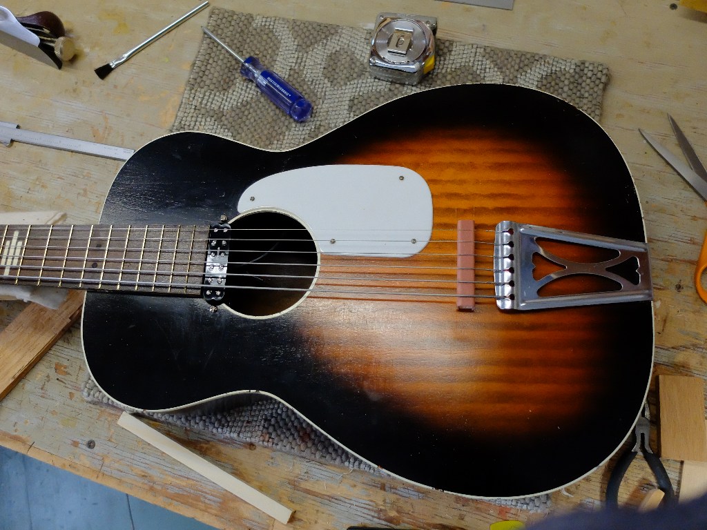
Rubber Bridge Experiments

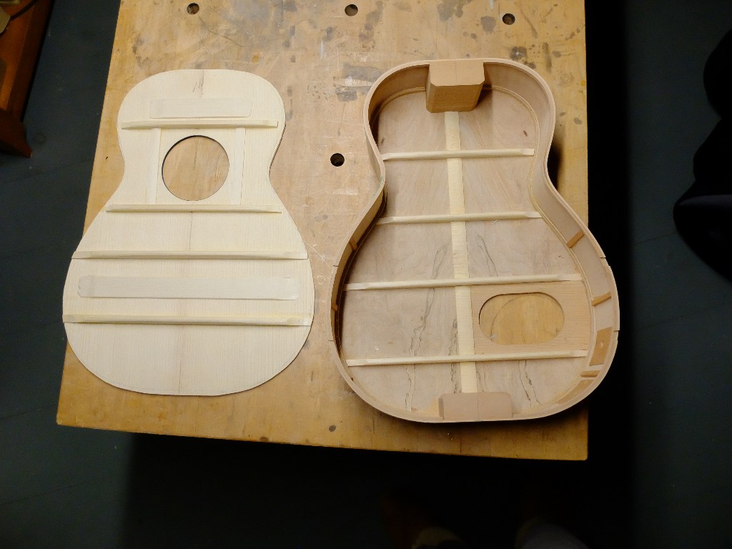
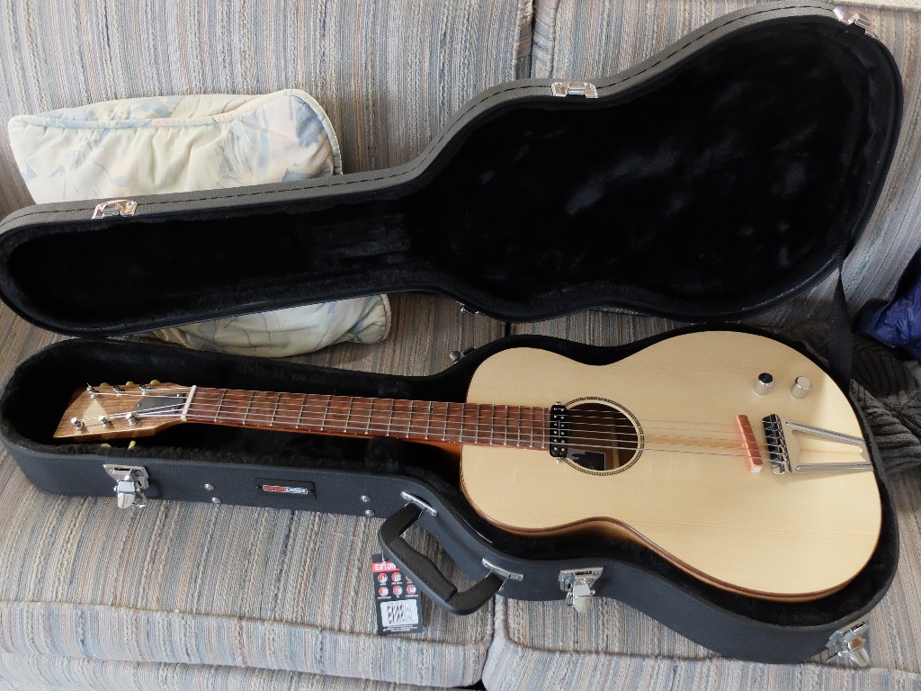
This blog is a continuation of two previous blogs starting with the Stella rubber bridge conversion pictured above. My impression of the Stella/Harmony guitar had a serious impact on me: it went pretty easily, and I therefore expected easy success in replicating this guitar, and the quality of the Stella built encouraged cavalier handling of lutherie ethics which were up to this point sacred ground for practicing builders. I set out immediately to build one from scratch, ignoring all my accumulated knowledge about using only quarter-sawn lumber, light weight top material – spruce of red cedar – for tops, tap-tuning, etc. This one is made from flat-sawn cherry, complete with bark inclusions, and thicknessed to about 0.150″. Inside of top: Heavy braces with layout and dimensions copied from Stella.
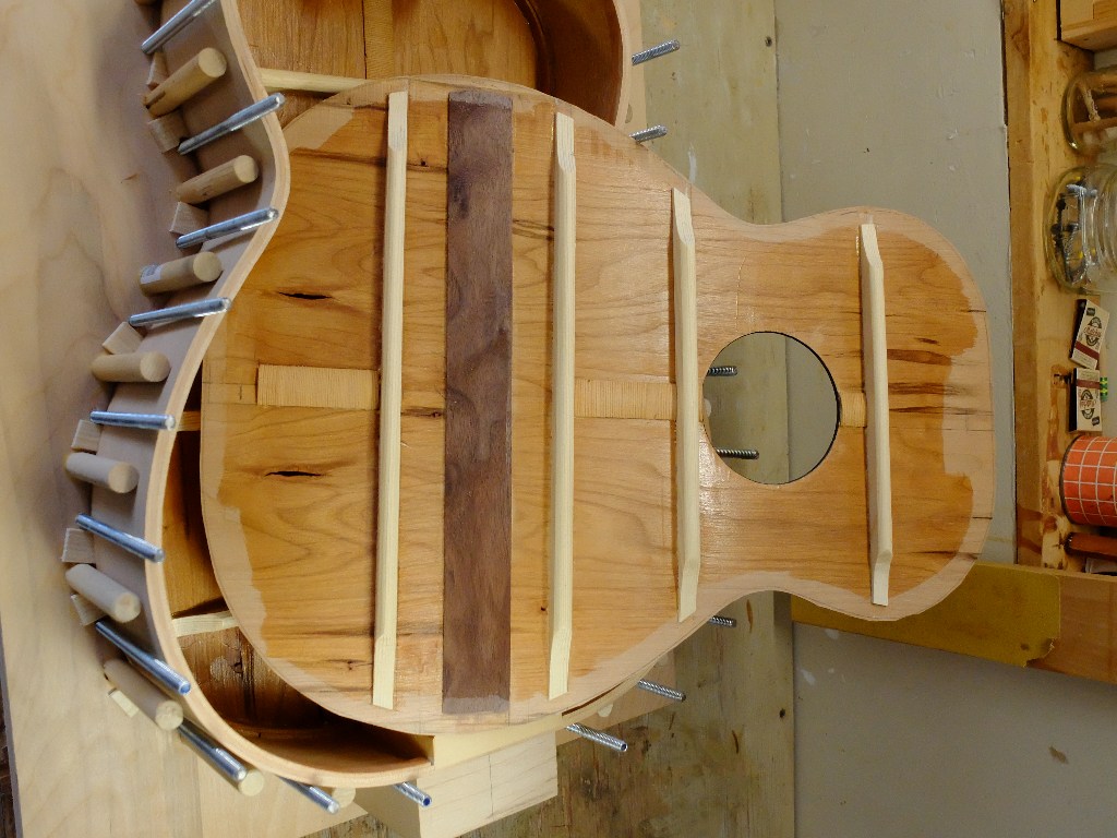
I did take the precaution of giving the insides a seal-coat of shellac in an anticipation of controlling dimensional change with humidity which the flat-sawn lumber should be more reactive to than quarter-sawn.

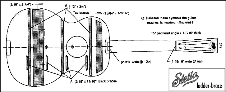
I could not find other documentation of Stella bracing, except this – which reinforced my impression that resonance was not a feature necessary for this instrument – 3 top braces at 1/2 x 3/4″ with a couple massive flat braces
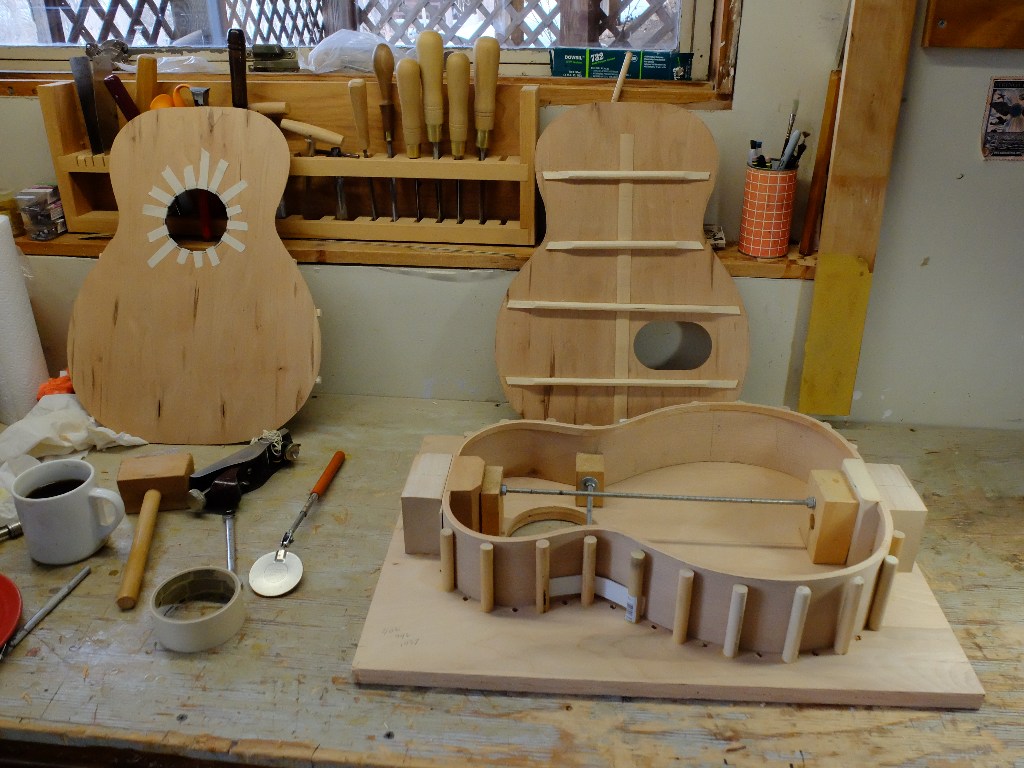
The back and sides of this new instrument are also cherry, quarter-sawn for the sides, but flat-sawn back. Here is the back ready to be glued on, with the access hole already cut. The top is on the left. I do use bent solid wood lining which takes a little more effort than the store-bought kerfed stuff – I think the end result is superior, and I can’t stand to pay $24 or something for the kerfing.
This instrument turned out great too, like the Stella conversion. I used the same pickups – Seymour Duncan Little 59 Strat mini-humbucker at the neck and the K&K Big Shot piezo under the bridge. Like the Stella, it took several trial placements before finding the best spot for the piezo, and I had to use the very thin double-sided tape that comes with the K&K for the attachment instead of the 3M foam used on the Stella, but it worked.

Success #2. Look for this one on stage if you are at a Guster concert. I thought I had it down. I accepted an order…
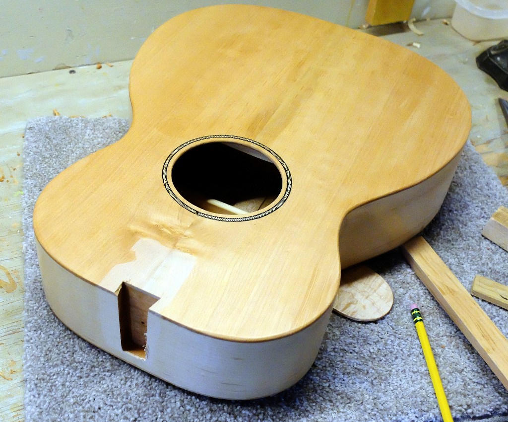
Building on the (now-mistaken) idea that resonance didn’t matter, I made the next one out of maple. Nice quarter-sawn back and sides, and flat-sawn big-leaf maple top. I used the Stella bracing dimensions.
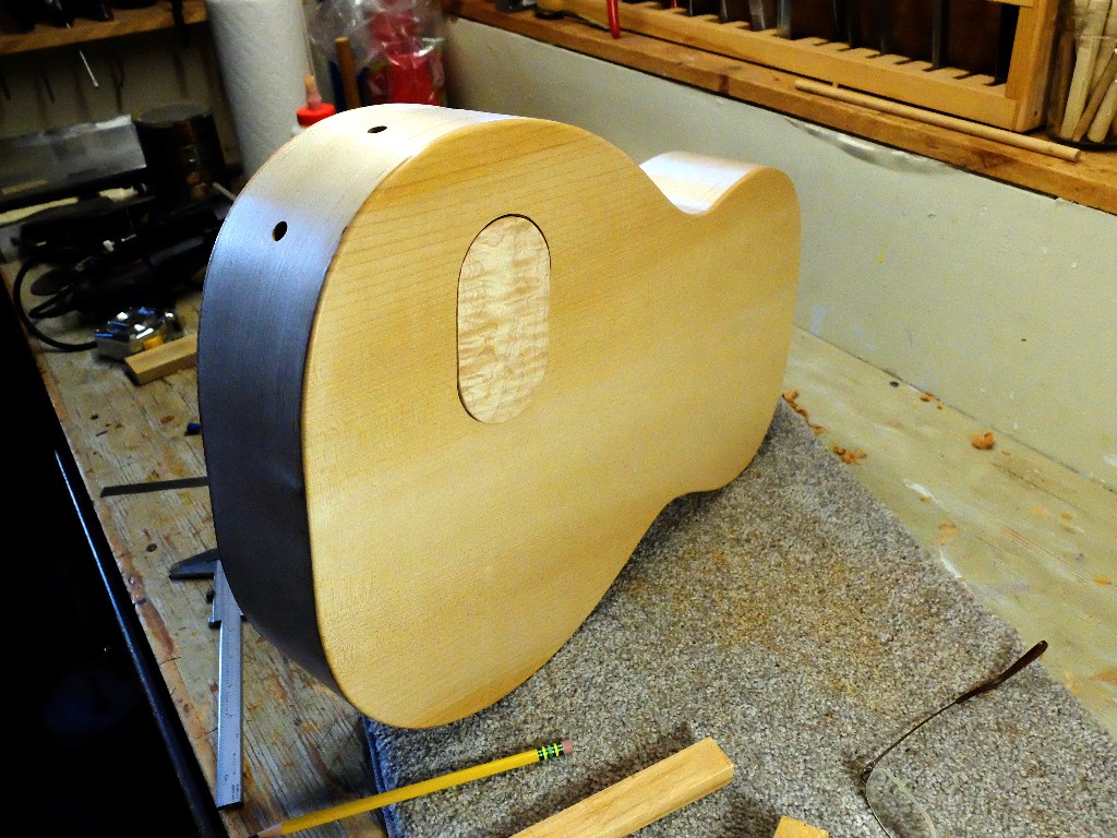
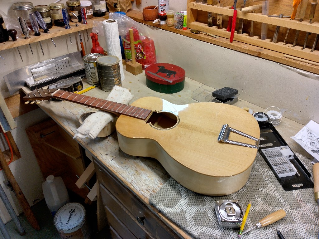
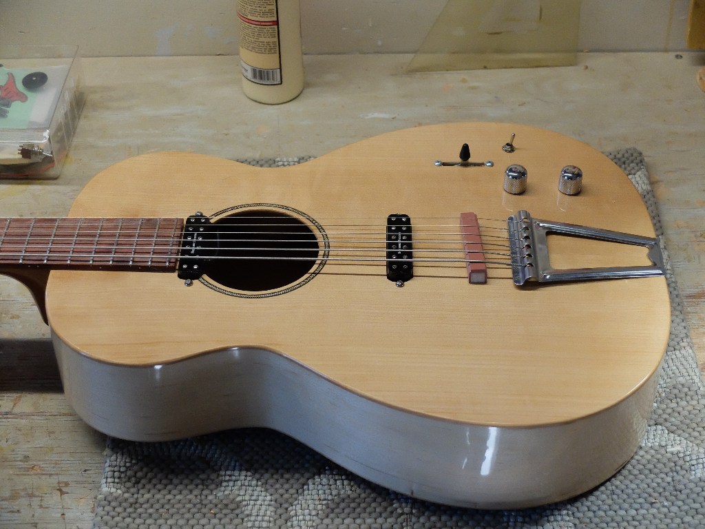
And it didn’t come out – that is, I couldn’t get the piezo to produce a signal that even came close to matching the humbucker. It was too dead. I switched to a dual-humbucker configuration wired like a Telecaster, but with a toggle that can send the bridge pickup out its own jack (I had to use the second output jack for something). Success, but not what the customer ordered. I refunded the deposit check, thought I had learned what it takes, and built another.
This next one has a spruce top, although a rather funky specimen from a tree that came out of somebody’s yard in Shelburne Vt about 15 years ago that I got from Roger Borys. I thinned the top braces and used spruce for the under-bridge reinforcement.
The back is a nice piece of spalted/quilted/curly big-leaf maple from Oregon
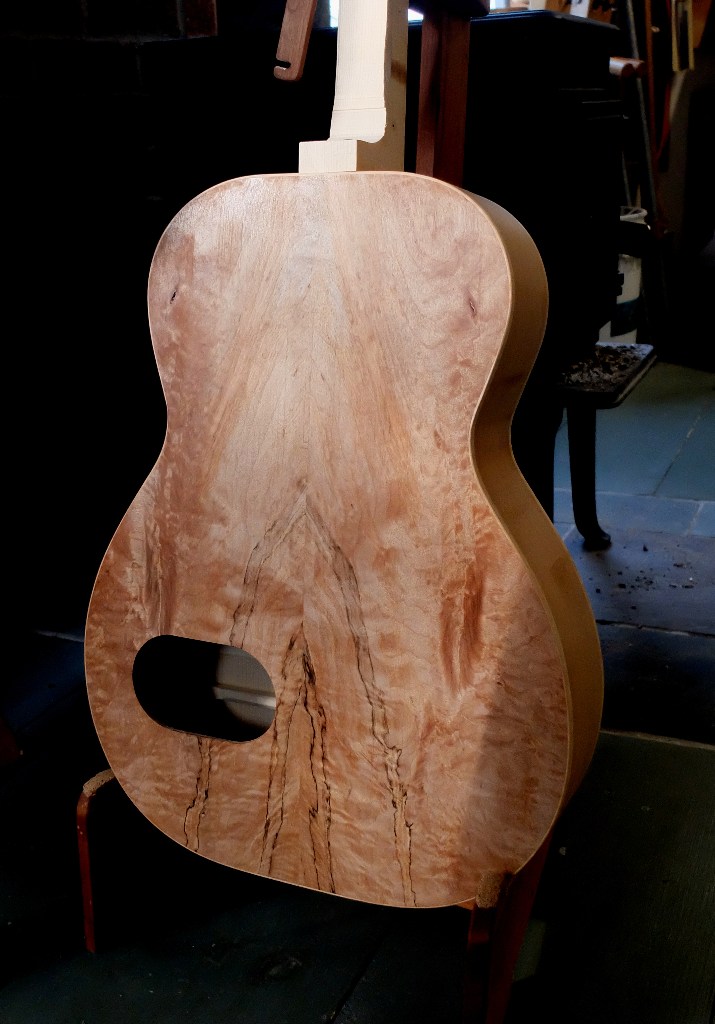
Cut to the chase – this didn’t turn out either. Piezo a no-go. I did the same dual-humbucker setup as the first ‘failure’, but this time moved the bridge pickup closer to the bridge for more bite, which necessitated raising the pickup in a nice little ebony mounting ring to get even balance between the two humbuckers. I now have in my inventory two interesting examples of rubber bridge guitars in a 3/4 size that have a lot of personality and attitude. Not a bad problem to have. I am trying again.
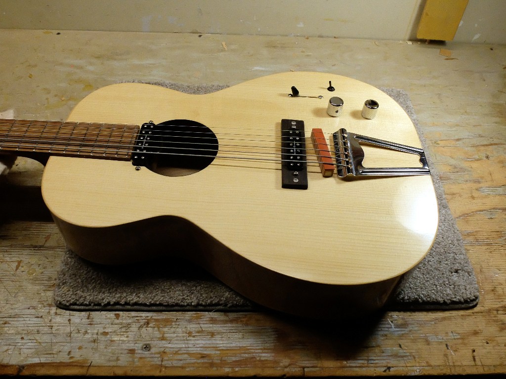
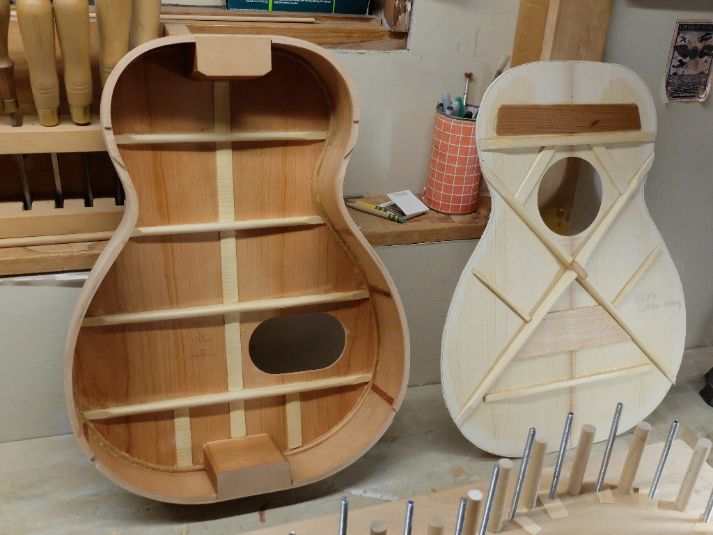
This one is a no-nonsense acoustic instrument called ‘The Hope’. I used real European spruce for the top (from Metropolitan Music in Stowe) and an ‘X’ brace pattern. The back and sides are cherry, quarter-sawn. The top has ring to it. It is in the final finishing stages and I will be able to string it up in about 2 weeks. I will post the results.
Results – I have to accept the fact that a piezo pickup cannot match the output of a magnetic pickup without a preamp. Almost all references to piezo’s recommend a preamp. This guitar, ‘The Hope’, worked with the piezo, but the signal was nowhere near balanced with the output of the Seymour Duncan magnetic. So – I abandoned the piezo, not being interested in a lot of tweaking to come up with a janky piezo sound, and just went with the single magnetic pickup with volume/tone controls. The result is an elegantly clean-looking instrument with lots of tonal capability and ready playability without a lot of gear messing around.
Rubber Bridge Guitar

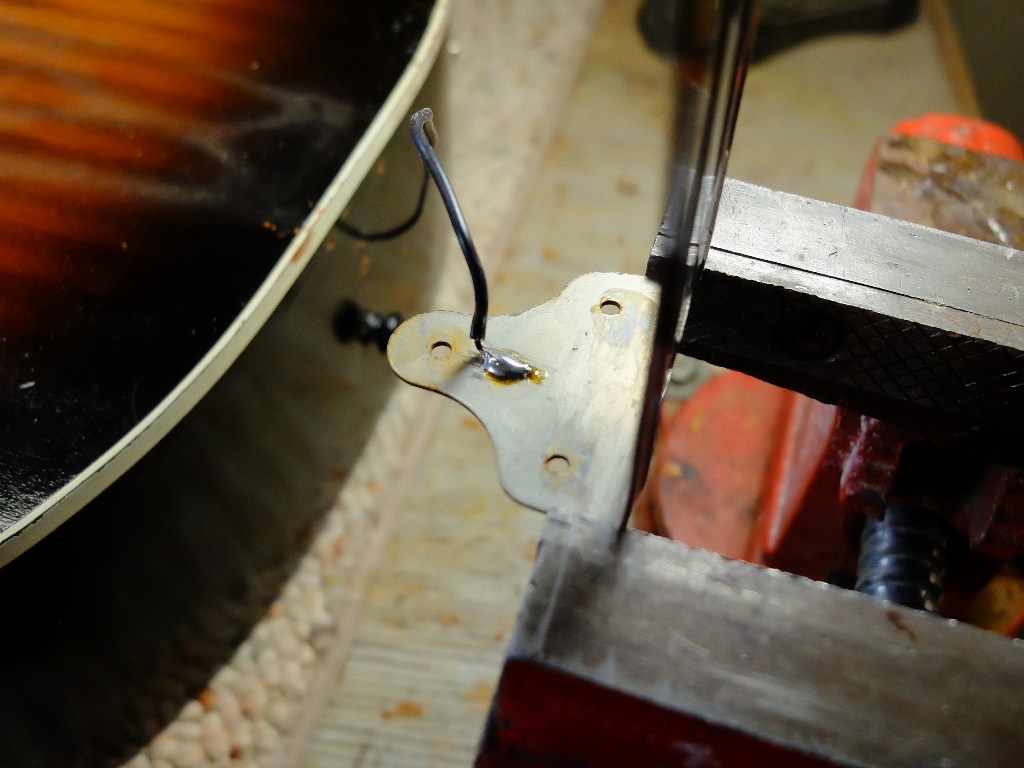
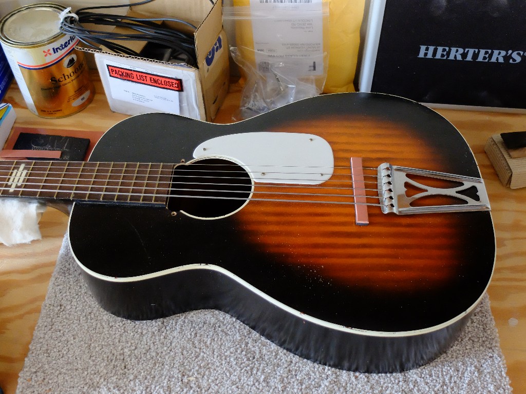
If you buy a rubber bridge guitar it will cost about $1,000, or, for about $250 you can get one of the cheap Stella’s that are mostly used as the base instrument, add a couple pickups, and voila. A client brought me this Stella to convert. To work from, we had one of the guitars that Reuben Cox had put together. Conversion was pretty straight forward. There are two pickups each wired separately to its own jack with no controls, and the wiring needs to include a ground for the tailpiece –

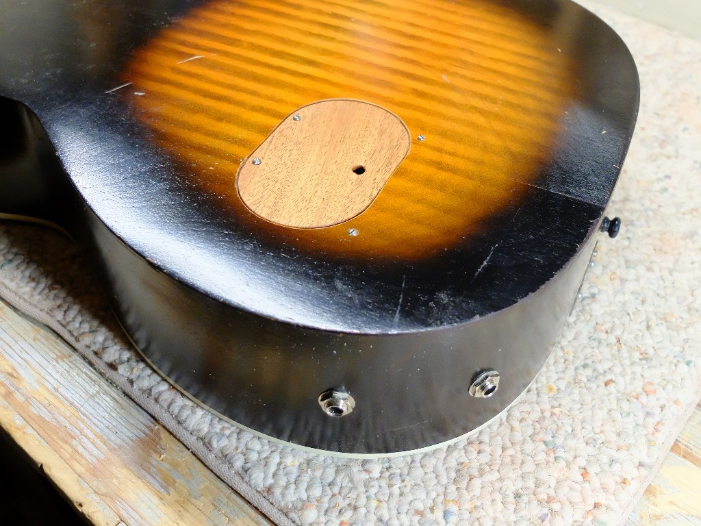
The output jacks are centered in the lower bout on the ‘away’ side – and we found that an access hole on the back greatly assists the wiring, especially since the Piezo pickup placement is determined by a hunt-and-see approach.

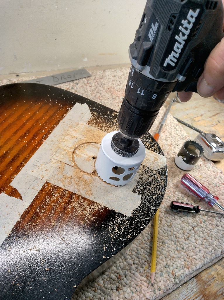
Given the journeyman quality of materials used on these Stellas, I had no problem resorting to the same hole saw I use for roughing in plumbing to cut the access hole.

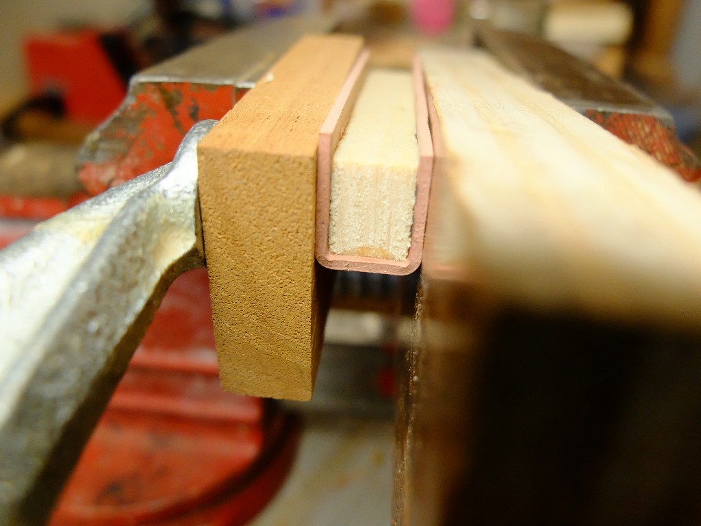
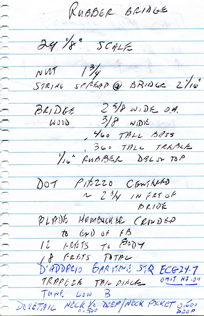
The bridge is made from a piece of pine wrapped in 1/16″ utility plumbing rubber sheet available at your local hardware store in the plumbing section. Picture below of gluing the rubber – cyanoacrylate (crazy glue) works well. I made the pine 3/8″ wide, about 2-7/8″ long and height according to action.

The pickups we used were a K&K Big Shot and a Seymour Duncan ‘lil 59 strat neck position mini humbucker. The fingerboards on the Stellas are flat, so that in theory dictates an adjustable pole-piece pickup, or one with a flat blade, but in our short experience that didn’t matter. The piezo, at least the Big Shot, is very hot and it took two or three trial placements to find one that gave a balanced sound. We used 3M double-sided foam tape, like you might use to attach a wall calendar to your wall, instead of the very thin tape that comes from K&K because we needed to tone the piezo down. The foam tape is removable to an extent allowing trial placements. This one ended up between the bridge and the tail block just to the bass side. The neck pickup is crowded up to the end of the fingerboard and requires some fancy woodwork at that end of the soundhole.

We used baritone strings tuned to a low B, omitting the top string from the flatwound 7-string D’Addario ECG24-7set. Here are my notes from the one we measured. Play the outputs into different amps, etc.

Stella Harmony Neck Reset

A client brought me a Stella Harmony to convert to a rubber bridge, and it needed a neck reset. I will cover the rubber bridge conversion in another post, but wanted to show the neck reset itself. These are incredibly cheaply made instruments with plywood top and back, braces just short of 2×4 framing, liberal use of adhesive like hot-melt glue, paint-on binding – which is why they are the favored base instruments for the rubber bridge conversion. The rubber bridge intentionally avoids resonance and overtones; the deader the better. The fact that the Stellas are common and inexpensive helps. This particular instrument cost $225 with case and shipping. Paying luthier wages to reset a neck doesn’t make a lot of sense – in this case, a DIY project makes it doable.

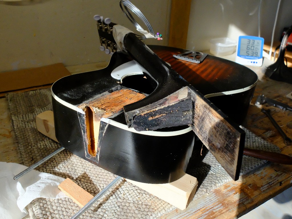
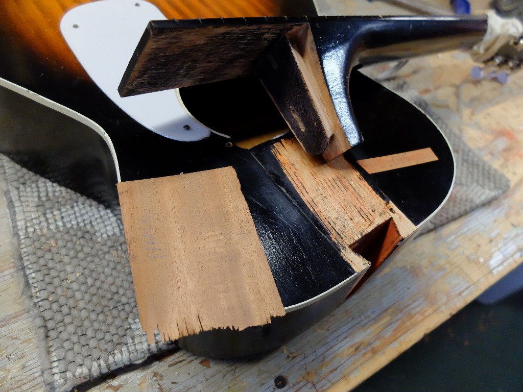
This is a normal neck reset. Unglue the fingerboard tongue, steam the dovetail, pop out the neck, refit and reassemble.

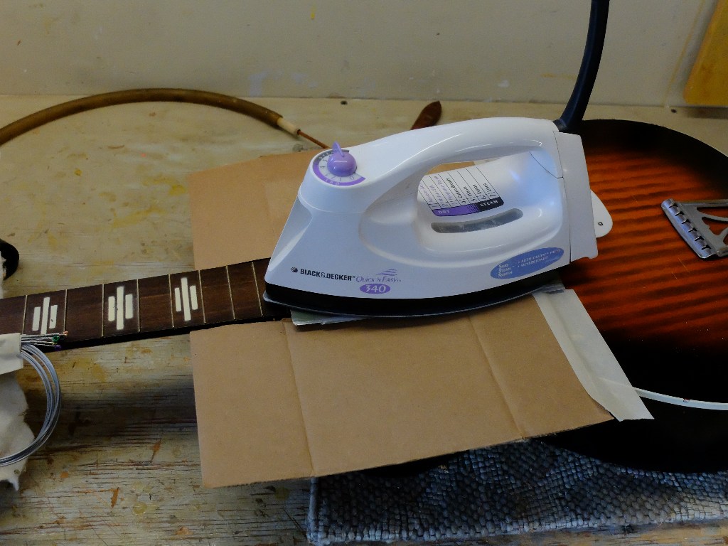
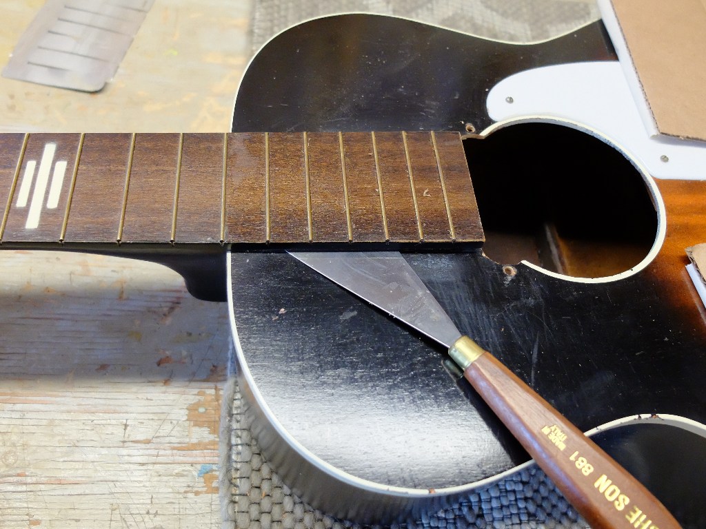
I use a clothes iron to heat the fingerboard tongue with some cardboard to protect the top finish, and then work a seam separation knife under the tongue.

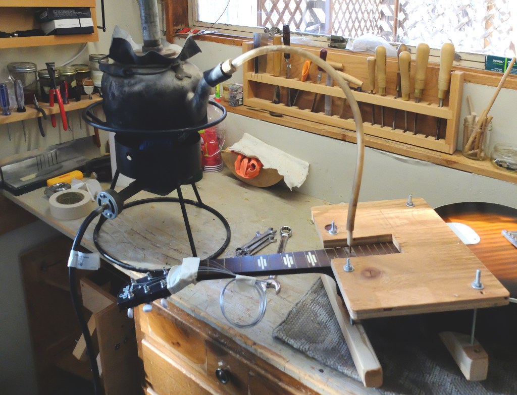
Knowing the size of the dovetail helps with where to drill the steamer access holes – this dovetail is 1/2″ deep, so holes drilled about 9/16″ in from the body joint hit the space between neck and body pocket. I was not concerned about hiding the steamer needle access holes, just plugged them when finished. In keeping with the basic aesthetic of the whole instrument.

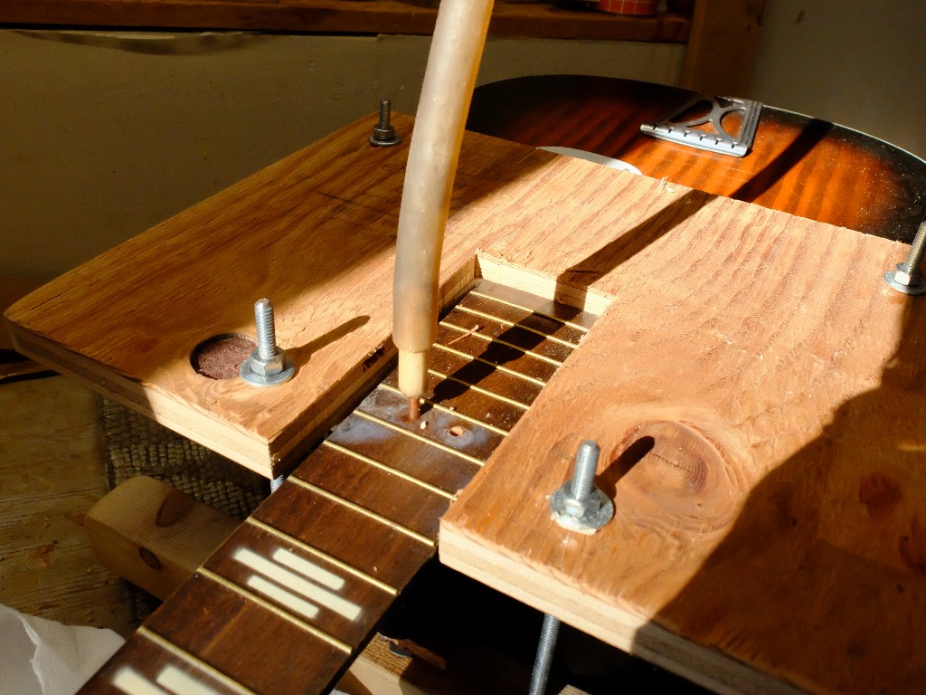
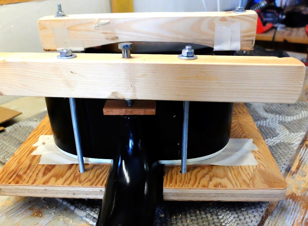
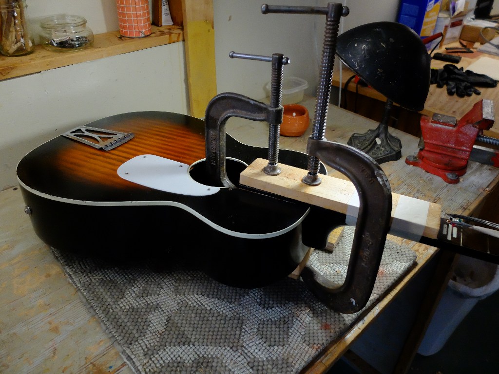
I made my own neck disassembly press out of plywood, padded at top and bottom contact points with cork, and held together with redi-rod, with a press bolt for the heel of the neck. Applying increasing pressure on the bolt pops the neck out as the glue softens.

I needed to add material to both sides of the neck dovetail to get a good fit, and a rather hefty shim under the tongue to get gluing contact with the top. These tapered shims that go to nothing are made on my thickness sander using a tapered backup block. I always use shims for the dovetail fitting, and colored chalk to see the contact points, starting with a shim that allows a snug hand-press fit that completely seats, and then making a shim .005″ thicker for the final glue up.

Once back together, the frets needed dressing. There is no adjustable truss rod, so whatever bow the neck had remains. Working on one of these is like an old house – you have to decide when to stop tearing things down and live with what you’ve got.

Torqeedo Electric Outboard on a Grand Laker type canoe

Putting an electric outboard on my motor canoe is appealing for a few reasons. First, compared to a gas outboard, the electrics are quieter, and the ones with lithium batteries are lighter. They are more easily carried in that you don’t have to worry about spilled gas in the car and there are none of the cautions necessary with transporting 4-strokes in how you place them to prevent crankcase oil from flooding the engine. They can run at slower speeds for trolling. I tried a Minnkota motor on my Grumman canoe but sold it because of the battery weight – it was as heavy as my 6-hp Yamaha 4-stroke. I took a leap and bought a Torqeedo.

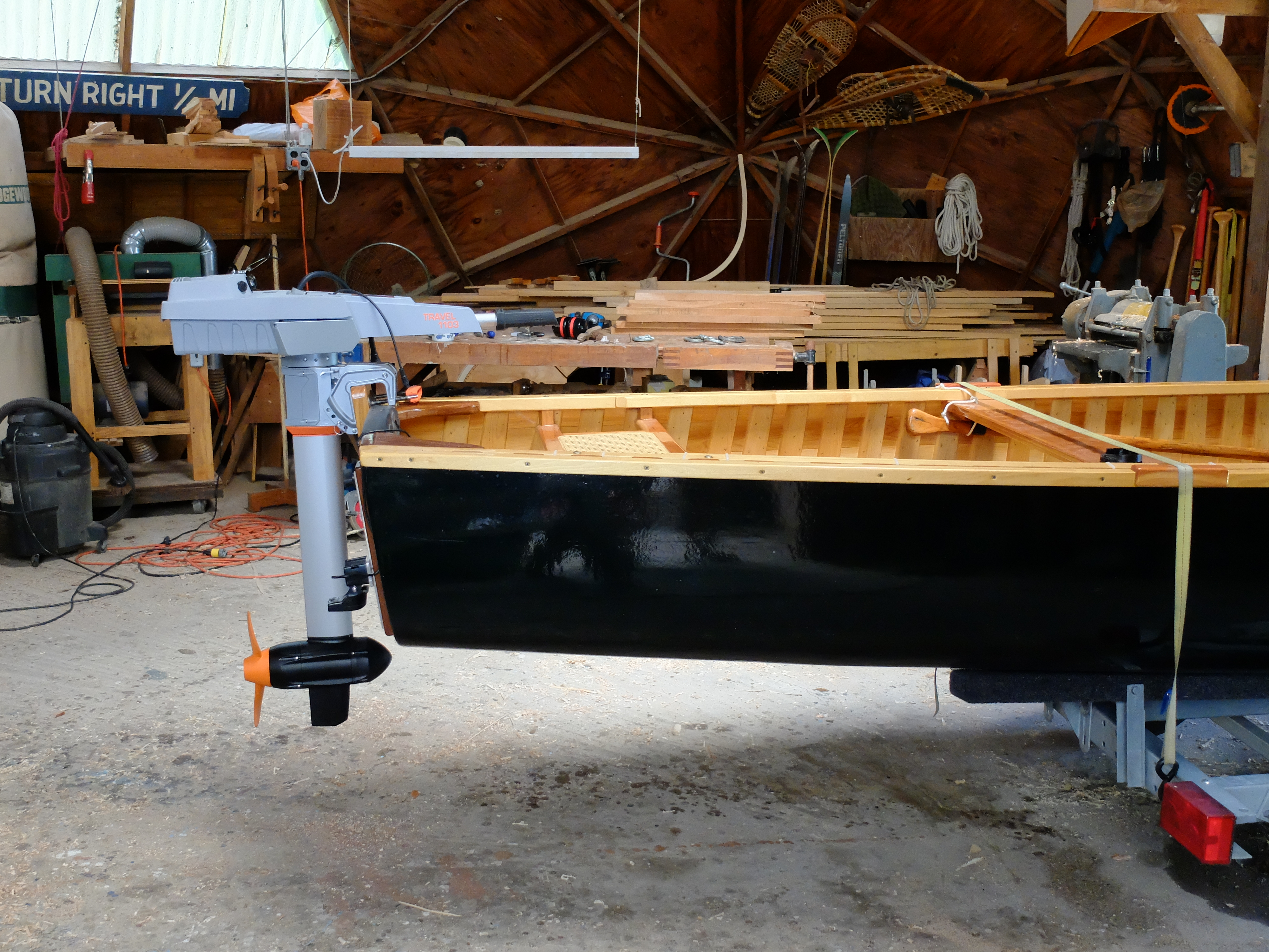
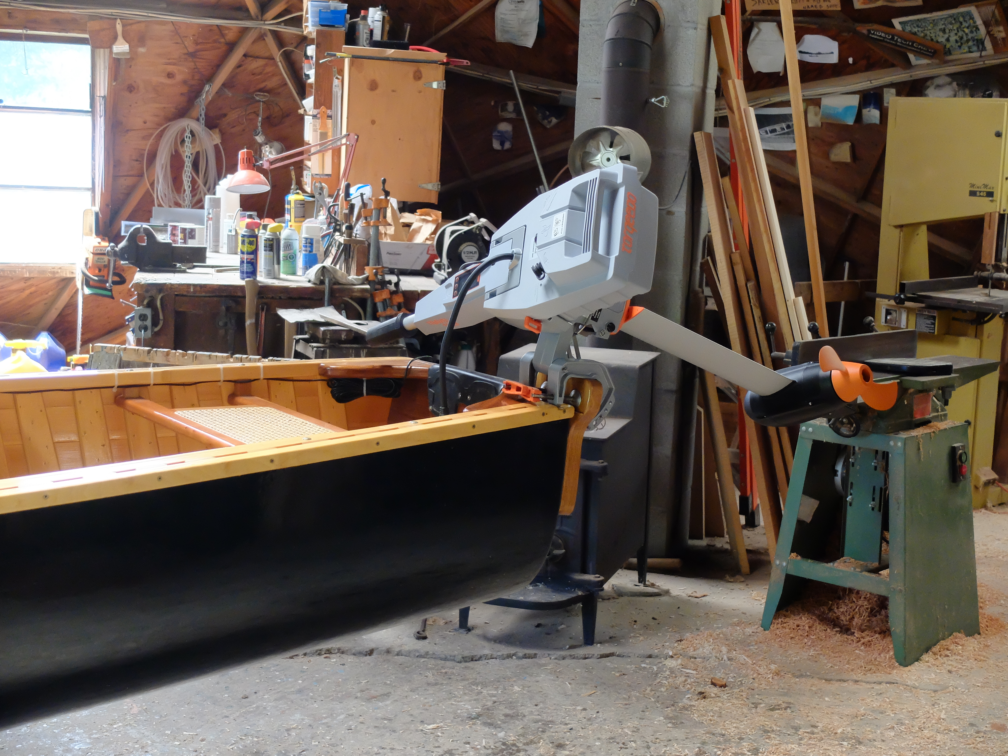
It has a lithium battery. It separates into 3 pieces for transport. It has a nominal 3-hp. It took some doing to get it installed on my canoe.

First, the tiller of the Torqeedo is centered on the motor, unlike a gas outboard with the tiller on the side. With the gas motor, you can center the motor and sit more or less on center and comfortably hold the tiller, which you cannot do with the electric. This setup ruled out putting the Torqeedo in the same position on the transom as the gas motor, so some kind of mount to one side was needed. The second peculiarity of the Torqeedo tiller is that is doesn’t functionally tilt up, like a gas motor. In use, it has to remain straight out, because if you tilt it up is comes out of its mounting bracket. It is designed this way to make the motor easy to disassemble for transport, but inconvenient for tilting – so, besides putting the motor to the side, you also have to be sure it can tilt since raising the motor when beaching or avoiding rocks is the order of the day with a motor canoe. Because of the battery weight on the back of the motor, it will naturally twist to one side as you tilt it, but you have to take some care in making this maneuver.

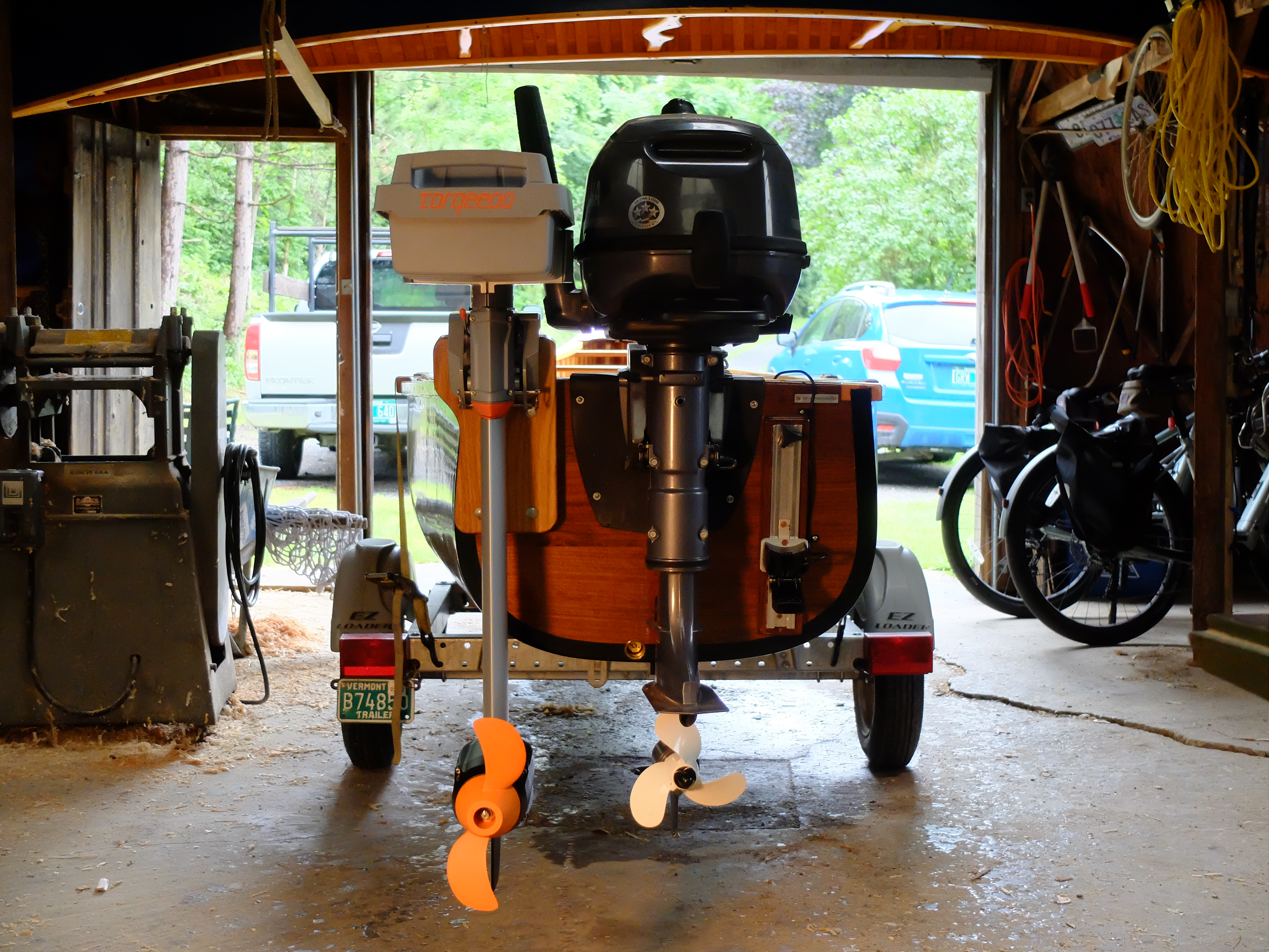
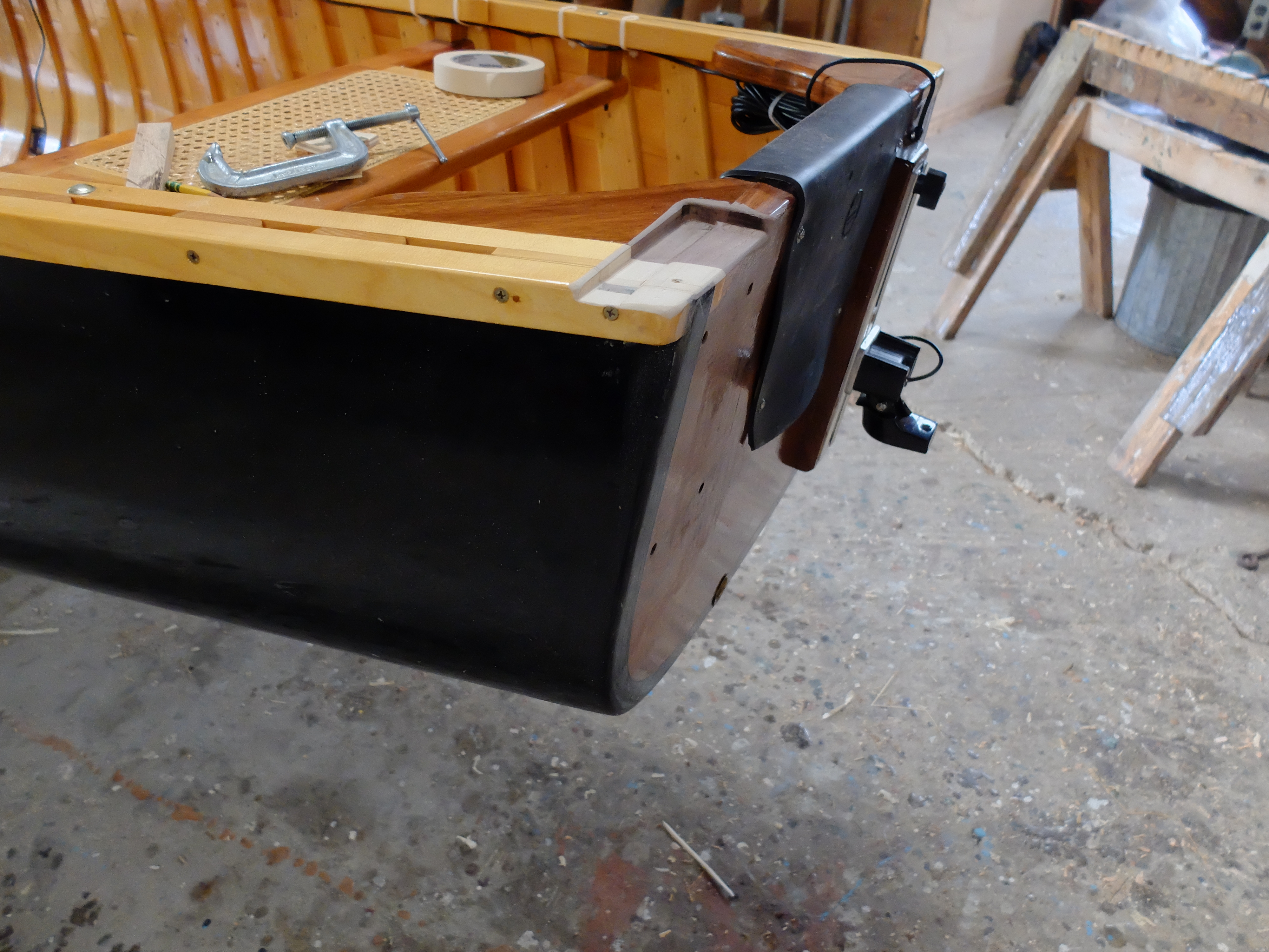
The second problem is getting the prop deep enough to avoid cavitation. News to me, Torqeedo’s 2 shaft lengths – ‘short’ and ‘long’ – are not exactly comparable to what we are used to in the gas motor world as short and long. The Torqeedo short is a good 2-1/2″ longer from top of transom to centerline of prop than the Yamaha. It was not immediately apparent why this was, so I made my first bracket for the Torqeedo to match the prop centerline height of the Yamaha. I made a white oak mount through-bolted to the port side of the transom, 2-1/2″ taller than the transom, so the centerline of the Torqeedo prop was as the same height as the Yamaha –

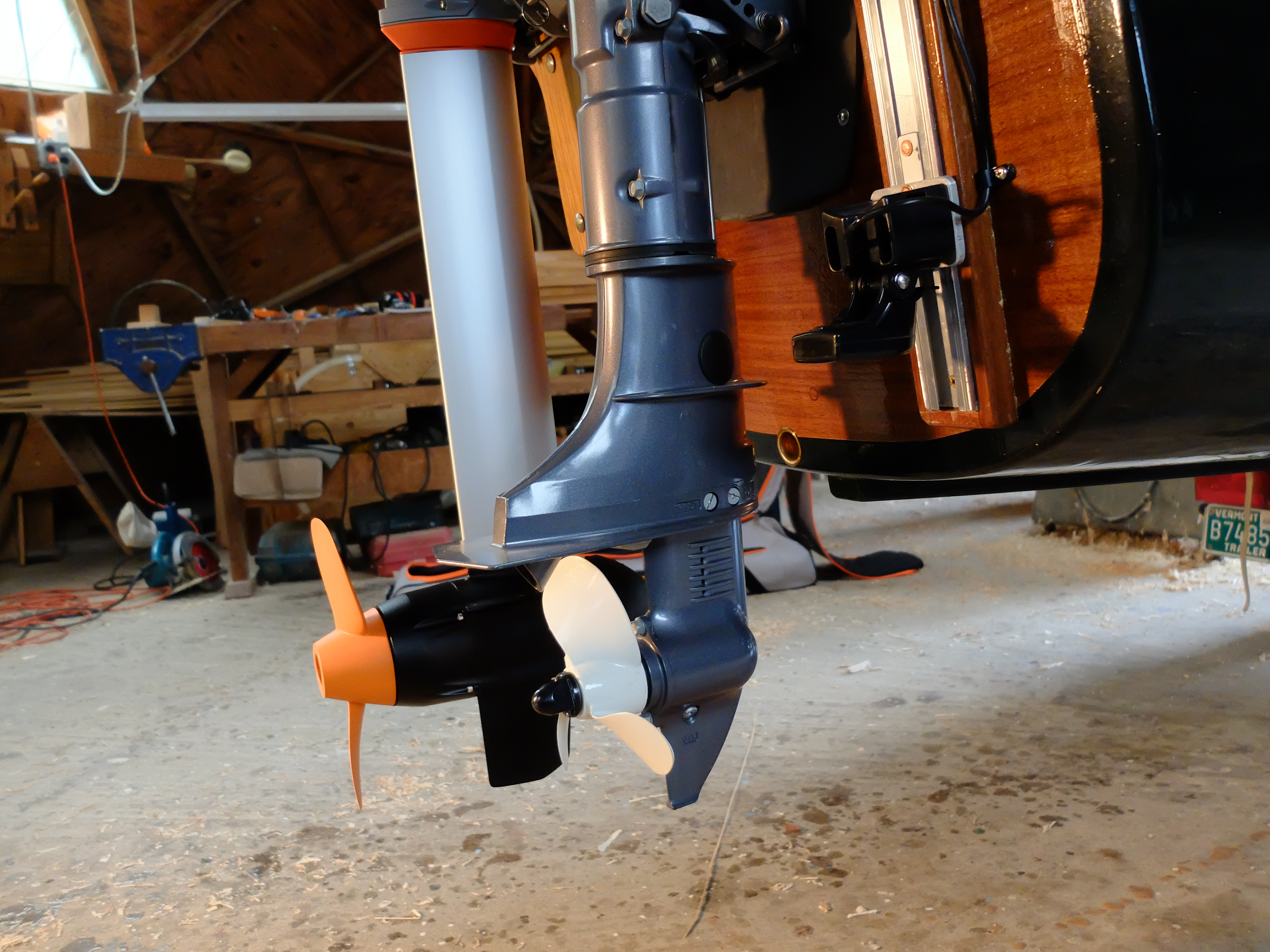
I made sure the top of my add-on mount would not interfere with the tiller of the Yamaha. Two obvious differences are the prop sizes – the Yamaha is 7-1/4″ diameter while the Torqeedo is 10-1/4″, and the shaft length previously noted. Also, the underwater bulk of the Yamaha is significantly smaller than the Torqeedo, which includes the full motor, and further, the Yamaha has an anti-cavitation plate which the Torqeedo does not. When I took it out for a test drive I found that the prop cavitated at any speed above 5 MPH, and that was only using about one-third throttle. There seemed to be lots more power to the motor which wasn’t being put to use and certainly nothing equivalent to the Yamaha which was happy at full throttle and 14 MPH. On the plus side, it slid along at 2-3 MPH almost silently and would do that for probably 8 hours on a single charge, and could be fine adjusted to optimal trolling speed without the noise, vibration, trolling bucket etc. rig I use with the gas engine.

‘Research’ revealed that electric motors turn at slower speeds than gas, and need larger props to be efficient, and I hadn’t provided the minimum requirement of 1-1/2″ of water between the top of the prop and the bottom of the hull at the transom (this is not stated in the Torqeedo manual). I only had 3/4″. Ah-ha! That is why the shafts are longer on electrics. I had to lower my mount. There was only so much I could do while still retaining my transom corner braces, but I was able to lower the mount by 3/4″ by cutting out a recess for the motor brackets.

The motor can still tilt, albeit carefully, and I have 1-1/2″ between top of prop and bottom of hull, so things should be better. I will try it as soon as it stops raining.

I had the boat out for a few days fishing. The Torqeedo performed perfectly, using only 30% of its battery over 8 hours of speeds around 2 MPH. It still won’t push the boat above hull speed, and battery use increases significantly as speed goes up, but that is not what I want it for. I don’t hesitate taking it out for a whole day with just the Torqeedo, knowing what I can get out of a single charge. One thing I did find out is that the plastic pin securing the battery will sink if dropped overboard – nice that it is bright orange.

Delta Belt Sander Motor Repair

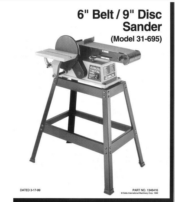
My belt sander, which I bought new in 2001, is one of the most-used tools in my shop. In 20 years I’ve only replaced the drive belt and the capacitor once, each. Last week however it slowed down while running, came to a stop and refused to start. When I hit the ON switch, the motor would turn a fraction of a revolution, make a buzzing sound but not come up to speed – no starting torque. It has a start capacitor which seemed like a fair place to start, but after replacing it with a new one, there was no change. I had to learn something about the motor.

(Always assume that a capacitor is charged with potentially lethal voltage. The two-pole variety like the one used for this motor can be discharged by shorting the poles to each other with an insulated handle tool.)

The motor – how to get it out. Removal of the bottom cover plates is straight forward. The motor is hung on a press-fit rod that runs from the front to the back of the casing, making the belt self-tensioning from the motor weight. There are 2 C-clips on the rod that have to be removed to drive the rod out. It is best to drive the rod from back-to-front (switch side) to get it out. This is not apparent from parts diagrams which show the rod coming out the back – to my misfortune since that is how I drove the rod out on my first try, slightly damaging the casing in the process. Obviously, supporting the casing by backing up the part that you are banging on is a good idea. Once the motor was out, I could test it on the bench.

Besides the capacitor, there is only one other part in the electrical circuit that could be failing besides the motor, and this is a relay in the switch box where the capacitor is. With capacitor start motors, the capacitor supplies additional current at start-up, which must be cut back during run. Sometimes the cut back is accomplished with a mechanical / centrifugal switch in the motor. Sometimes it is done with a ‘potential relay’ that energizes two circuits, then cuts one off as the motor comes up to speed. The potential relay is the method used in this Delta motor. I was able to take the relay apart, look at the contacts, verify that nothing was sticking, and I was also able to rule out the relay by bypassing it and attempting to run the motor directly on the ‘run’ circuit with a pull-cord start. It behaved the same with the relay bypassed as with the relay in line – that is, it had no starting torque, if it turned at all.

In a DIY forum on the subject of capacitors I found a posting that was helpful. First, it said that in a situation such as this motor with an AC capacitor with just two lugs, there was no difference between poles in how they were wired, so I could not put the capacitor in backwards as I feared I might. Even more helpful to my situation was the information that a motor which turns freely without power but binds up when energized, as mine did, most likely had a problem with the rotor being off-center and hitting the inner wall of the stator. This appeared to be the problem.

The outside of the motor is 3 parts – the end caps which hold the shaft bearings, and the stator – which are held together with 3 long bolts. I found that getting these parts to line up exactly was the key. There is very little clearance between the rotor and the inside of the stator – probably in the range of 0.040″ – which makes precise assembly of the motor essential. The bearings are close to press fits in the end caps, and definitely press fit on the shaft. Heat used cautiously allowed me to get the bearings to seat in the end caps (there is a spring washer under the bearing on the off-pulley side) and I ended up using bar clamps to press the whole assembly together so there was correct alignment. I repeatedly tested the motor on the bench with different clamping positions until I found one where the motor both turned freely by hand, and started and ran smoothly. That is where I put the 3 bolts back through the casing and tightened them to within an inch of their lives. It has so far given 2 hours of runtime without failing.

Why it ran for 20 years and finally warped out of alignment I cannot say. I would probably not have gone through the hours it took to figure this out except for the fact that new machines are either very expensive, or very cheap, and used machines are hard to find. Our new-age era is one where repairing equipment is starting to make a lot more sense, now that we are in a supply problem with both new and old equipment.
Silvertone Jupiter Neck Specs

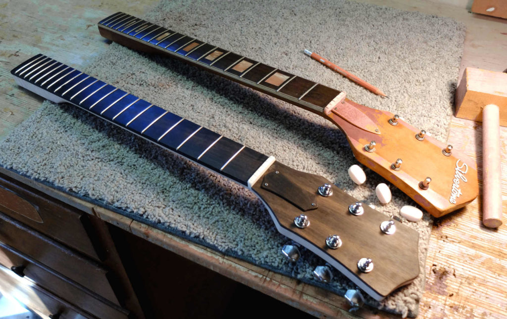
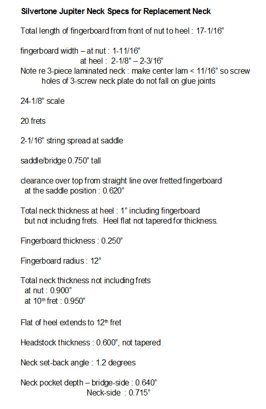
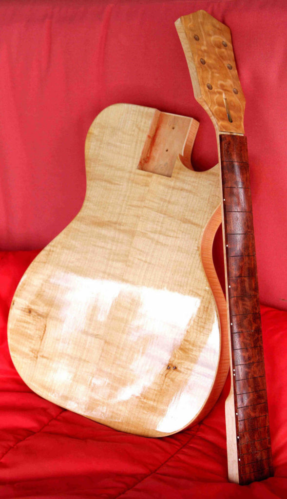
I am working on a Silvertone copy for myself. I’ve made four or five necks for these Silvertone guitars, working from measurements taken from three of the originals, and compiled the dimensions which may be of interest to other builders. Of the three originals I studied, none was exactly the same as the others, and even the scale length had to be guessed at. The dimensions shown here are those that I now use when I want to make one of these necks. In particular, mine are about 3/16″ wider at the heel than the originals, which were barely wide enough to capture the outside of the high and low E strings on the fretboard. Pictured above is an original, top, and my version, below. I also scale down the headstock by about 15% because the originals are oversize to my eye. These are the specs I use :
Created with GIMP

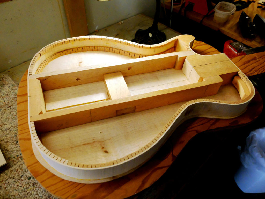
The guitar I am working on now is loosely based on the Jupiter model – I made it a hollow-body with a sort of ladder-truss arrangement down the middle to support the bridge and take the string tension. I used Spanish Cedar for those parts to keep things light. In the cutaway I used a small mahogany block so I didn’t have to try to bend the sides around the horn. The neck block is light mahogany. One of the things I like about these guitars is how light they are, and this one, even though it has 3/16″ hard maple for the top and back, is still pleasingly light.

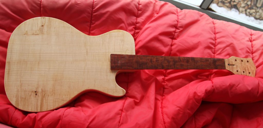
With the neck pocket cut out, and the neck ready for finishing and frets – I used as much curly maple as I could find, including a piece of big leaf quilt for the headstock overlay. Also needed a piece of highly figured bubinga for the fingerboard.

At the finishing stage now – having trouble selecting my material as always. Probably going to use Lollar gold foil pickups.

Lofting – Drawing the Body Plan from a Table of Offsets

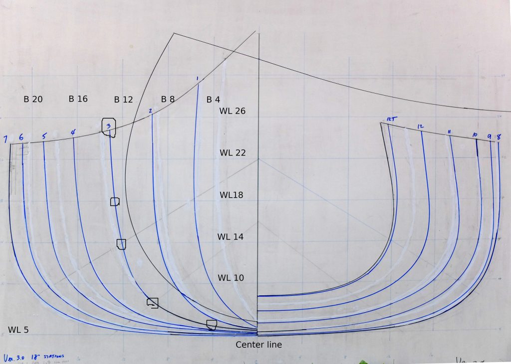
Lofting has two main objectives. The drawings represent the shape of the boat full size and so can be used to make templates for parts. Secondly, the drawings allow the builder to confirm that the shape of the boat will be fair, that is, without lumps and bumps. There are three views of the boat produced when lofting : the body plan, which is the boat viewed from directly ahead or astern; the profile plan, which is the boat seen from the side; and the half-breadth plan, which is the boat viewed from overhead. The image above is an example of a body plan. The curved lines show the shape of the hull at specific ‘stations’ spaced at regular intervals along the length of the boat. Commonly, the stations forwards of the middle of the boat are on one side and the aft stations are on the other side in the drawing. One of the main uses of a body plan is to make the forms that the boat is built on.

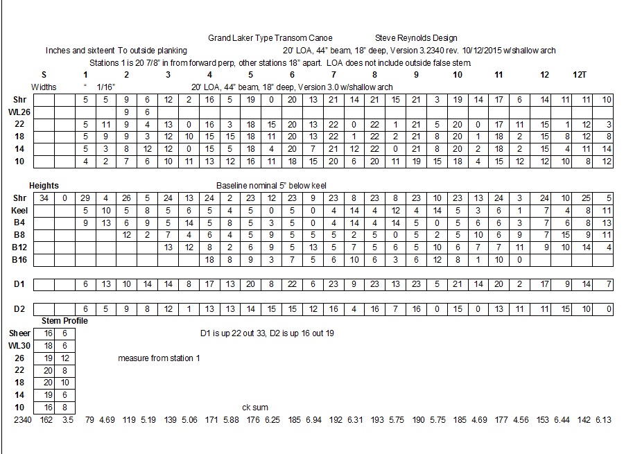
A table of offsets is the key to building a boat. It gives measurements to points which, when connected in a smooth curve, represent the shape of the boat at all the stations and in all three views. The table of offsets above is for my grand laker canoe design, which also is shown in the body plan above. There are 12 stations plus measurements for the S(tem) and vertical projection of the T(ransom). Station 1 is 20-7/8″ back from the forward face of the stem, all others are spaced 18″ apart. The measurements are in inches and sixteenths of an inch.

The first set of numbers titled ‘Widths’ shows measurements to points horizontally out from a centerline at different ‘waterlines’. Waterlines are horizontal slices through the hull at different heights above a baseline. The choice of waterlines is arbitrary but can make things easier or harder depending. In my design, I elected to establish a baseline about 5″ below and parallel to the mid-section of the intended keel, and draw waterlines parallel to the baseline starting 10″ above the baseline and then every 4″.

The second set of numbers titled ‘Heights’ shows measurements vertically up from the baseline at different ‘buttocks’. Buttocks are vertical slices through the hull parallel to the centerline at different distances out from the centerline. Again, the choice of buttocks is arbitrary, and I chose to draw buttocks every 4″.

The Diagonals D1 and D2 are a third set of measurements to check the fairness of the hull. Their placement is selected in an attempt to have the diagonal lines cross the station lines at close to right angles, and they are defined as being ‘X’ inches up from the baseline and ‘Y’ inches out from the centerline. The measurements are from the end of the diagonal on the centerline to the point at the desired station.

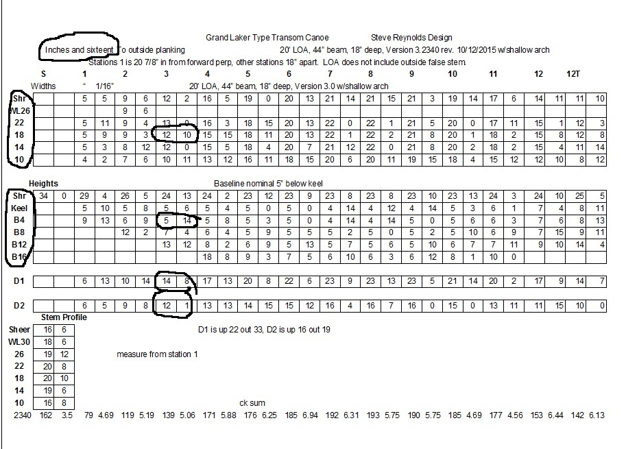
To begin a body plan drawing, a suitable surface is prepared – 1/4″ plywood with a coat of flat white primer is good – and for my boat, a piece about 42″ tall by 48″ wide is sufficient to draw the stations full size. The centerline, waterlines and buttock lines are drawn in and labeled and then you can begin marking the points for each station from the Widths, Heights and Diagonals. In the example below, looking at Station 3, we see that at waterline 18, the measurement from the centerline out is 12-10/16″ or, 12-5/8″. Station 3 height at buttock 4 is 5-14/16″, or 5-7/8″. Likewise, the measurement for diagonal 1 is 14-1/2″ and diagonal 2 is 12-1/16″.

Transferring these to the body plan, we get the points circled below. After all the points for a station are drawn, the points must be connected in a smooth curve, and this is done with flexible battens of various material – I use wooden ones in different sizes and you have to get creative about holding things in place while you draw the lines.

When you have finished drawing all the stations you have something – even if just a nice drawing to put on the wall. I will discuss the profile and half-breadth views in another blog.

5 Gallon Trolling Bucket

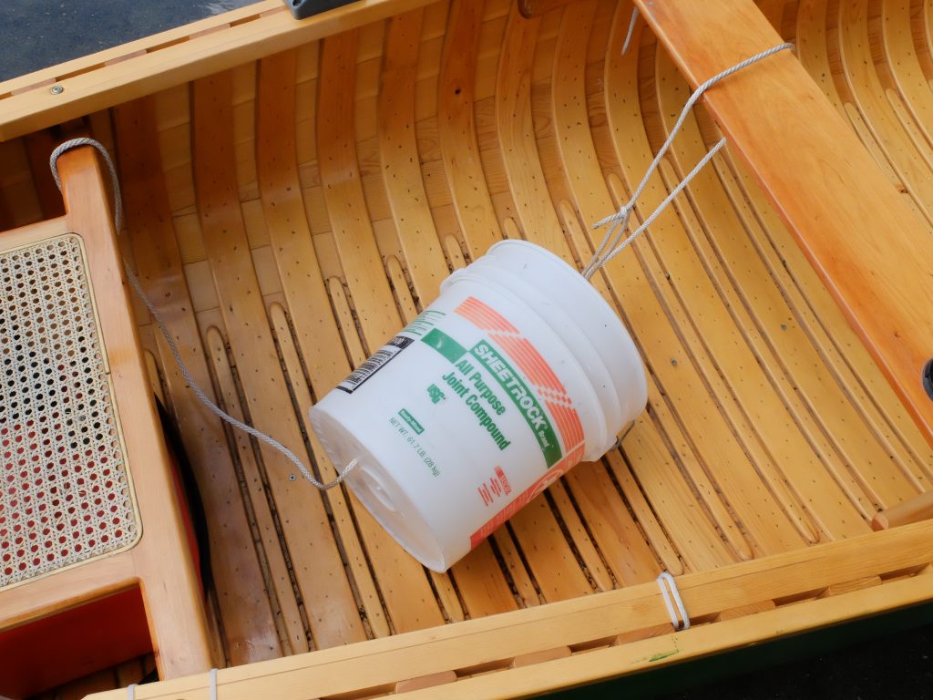
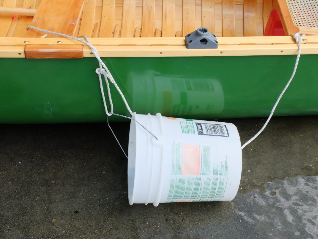
Controlling boat speed when trolling has a lot to do with catching fish, and until I tried this rig we had little success. My boat, with the 6 HP Yamaha at idle, is very easily pushed, and the best low speed I could get was 3.3 MPH. I considered all the options – trolling socks, trolling plates mounted on the cavitation plate, buckets off the stern, a smaller pitch propeller – this bucket setup work well, does not get in the way of the prop or fishing lines, is durable and costs next to nothing. With the bucket as shown, my speed can be controlled between 1.5 and 1.9 MPH just by changing the angle of the bucket in the water, by adjusting the fore and aft ropes. With the bucket angled up-at-the front, I get 1.9 MPH, with the mouth of the bucket down/level, I get 1.5. Setup is simple – a couple holes in the bottom of the bucket to pass a line through, and an 8′ length of rope tied to the handle. In the image below, the bow of the boat is on the right. The line goes around a thwart, through the bottom of the bucket, and tied to the stern seat.

When it’s over the side, it looks like this – now the bow is on the left.

When I want to retrieve it, I just tip it mouth down and drain and it all comes aboard still rigged up. The holes in the bottom only are useful for draining when I leave the bucket in the boat to store anchor line etc. Those holes are not for draining the bucket when I bring it back inboard.

The rig does affect boat handling, but in my case, with the single bucket off one side, it gives the boat a slightly sidewise stance that gives the person handling the fishing rod (from the opposite side of the boat) extra room for their line going past the stern and works to our advantage.

Lines of a 20′ Lake Champlain Sharpie

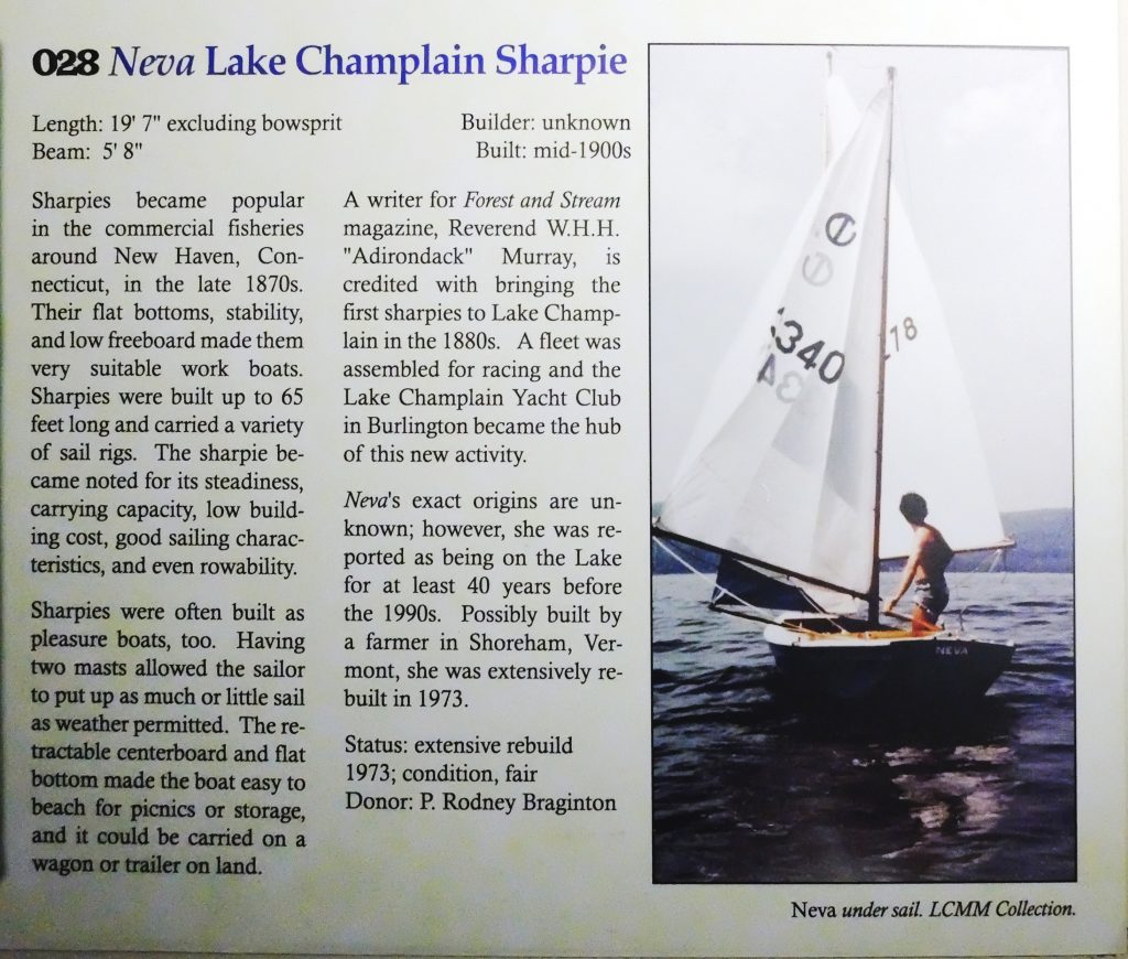
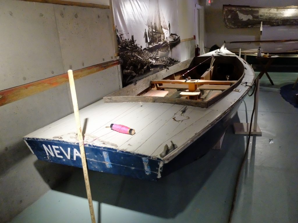
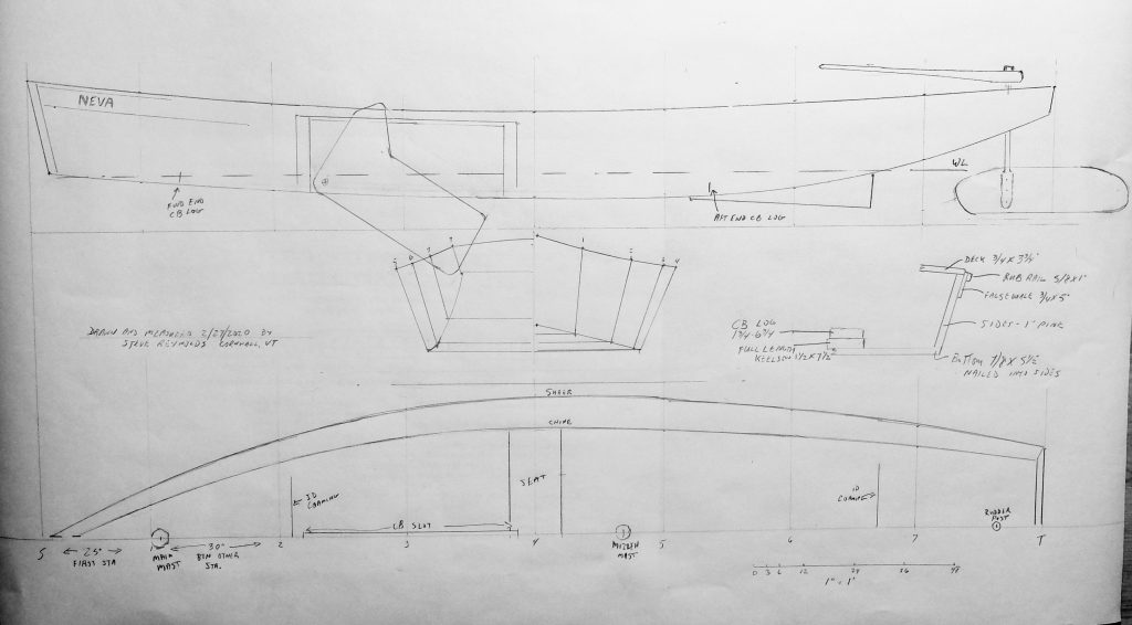
Neva had been lying in a field on the shore of southern Lake Champlain for a couple years when she was given to me in 1972 by the owner who had decided she wasn’t worth saving. She was thought to have been built in the 1890’s at a time when sharpies were popular on the Lake. Howard Chapelle has written extensively about the history and construction of sharpies in American Small Sailing Craft, Boatbuilding, and other books. He describes and shows plans for a sharpie that he measured in 1928 which had been built on Lake Champlain in the 1890’s for racing. The extreme development of these boats as racing machines shows that boatbuilders on the Lake were very familiar with the sharpie type, and makes Neva‘s undocumented lineage believable. Although the main area of sharpie building was centered around New Haven Connecticut, it is possible that the sharpie design originated in Vermont – in American Small Sailing Craft, Chapelle notes that a letter to the editor of Forest and Stream magazine in 1879 claimed that the first sharpie built in New Haven was by a Mr Taylor, a Vermonter. Chapelle’s racing machine was 35′ long and carried a crew of 12, nine of whom used springboards to counterbalance the boat’s heel and keep her on her feet. Neva, by contrast, is 20′ long, modeled more or less on the working sharpies of the Connecticut shore. It is possible that Neva is now the only surviving example of a traditional type once popular on Lake Champlain.

I didn’t know about the history of the boat at the time I got it. The deck was rotted and had to be torn off and rebuilt – in fact, only the side, keelson and bottom planking were in sound condition. The sides are single, width-full, full-length pieces of 1″ clear white pine – lending further credence to her reputed age. That kind of lumber is almost nonexistent today. I wanted a boat for exploring the Lake, and my budget was close to nil. The original rig seemed to have been a large-ish main mast placed at the front of the centerboard case with a small mizzen well aft – I set her up with a more balanced rig, I thought, using second-hand sails from, respectively, a Snipe, a Sailfish and a Turnabout, set on masts cut from some small spruce trees I found here and there. I added the bowsprit for a piratical look and nominally to support the masts; it was not, I’m sure, true to the original rig. Later on, I added an outboard bracket and a 1940’s vintage 5HP Evinrude motor. I used the boat for about six years, keeping it on a mooring in Bridport, Vermont. I was a biology student at UVM for part of that time, and conducted a study of the bivalve clam population of the Lake in the immediate area of my mooring and managed to feel connected with the boat’s ancestry by using it to ‘tong clams’, just like in the old days. I sold her in 1979, the year our son was born, and also the year I acquired my next boat.

That was about 40 years ago. At some point during that time I became aware that Neva had been donated to the Lake Champlain Maritime Museum. The display included photographs of both my wife and my youngest brother, which proof of association I enjoyed.

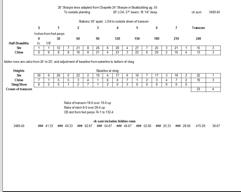
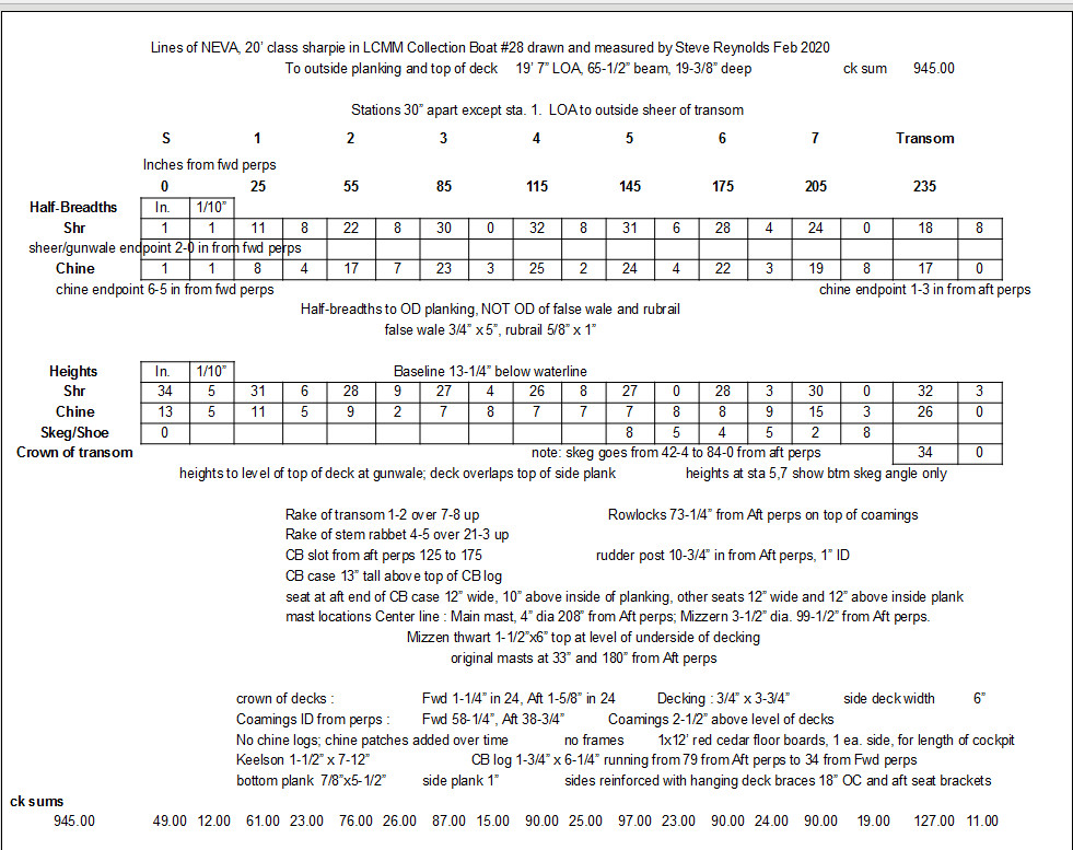
My interest in Neva revived this past winter (2019-2020) when I considered a new building project. My experience with her sailing qualities gave me no particular reason not to build one – the only time I ran into trouble with her, aside from one dismasting in a gust, was running downwind in a breeze and putting her foredeck under a wave as we overtook it. All designs have compromises, etc. etc. I started looking for a table of offsets for a twenty-foot sharpie – and came up with nothing I liked. Chapelle has lines for 24′ boats, which I tried scaling down to 20′, but the result looked exactly as one would expect – it was a scaled down version of a larger boat and the proportions, to function well, can’t all be scaled equally. That is, relatively speaking, the beam can’t be reduced in proportion to the length. I decided to take the lines off Neva and applied to the Museum for permission to do that. I spent a day and a half taking measurements, which I lofted at 40% scale (using the 1″=1cm method) to develop the table of offsets.

To illustrate my point about not scaling a larger boat down, below are the offsets for Chapelle’s 24′ sharpie, scaled down to 20′. For example, note how the maximum beam of the scaled-down boat is 4″ narrower at the sheer, and 2″ narrower at the chine. It looks pretty, but would not be a satisfactory sailboat.

I will go into some construction details in a future blog.

Lofting at Half-Scale Maine Utility Skiff

15′ Maine Utility Skiff

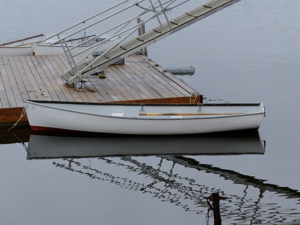
A place I go for a week each year on the Maine coast has a half-dozen utility skiffs that are understated gems.

They row well, have good carrying capacity, can take a low horsepower outboard, and sail fine with a simple sprit-rig if equipped with a centerboard. They can be beached and dragged off the rocks with the coming and going of the tide. It would be nice to have one for kicking around, and I decided to at least try to take the lines of one of them to document the design, and be ready to build one if I ever got fired up enough about it. I’m sure there are plans for similar boats available, but the process of drawing up your own lines is interesting. For the time being, I have left the decision of construction method undecided.

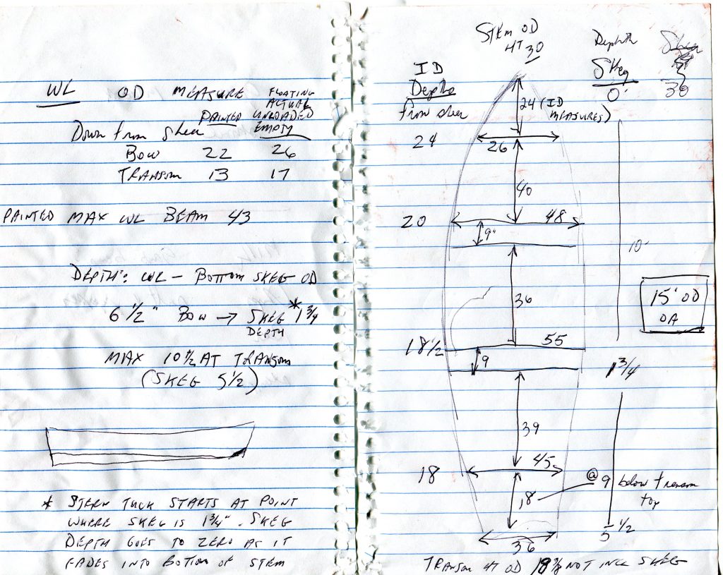
I made cardboard templates of the inside of the hull at two places, about 2′ ahead and abaft midships, as well as a tracing of the transom (expanded view). I got overall length, and beam at gunwale at four places, plus the transom. At those same beam locations, I measured inside depth from keelson to top of sheer.

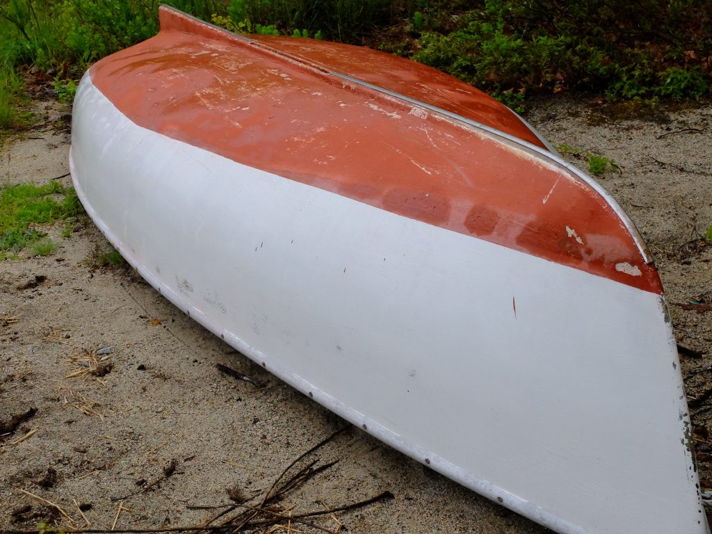
From a boat upside down in a field I got a look at the run of the keel, the amount of tuck in the stern, and some waterline depth measurements.

Most of these boats show some hogging in the keel, I believe caused by shrinkage of the fiberglass as it cured; the keel fiberglass areas probably got hotter due to more allowed to set up at once. The hogging is not a design feature, and I would not incorporate it into my design. This boat, above, had a centerboard.

Given the measurements I had taken, I was ready to start to draw the design and loft the lines to check for fairness.

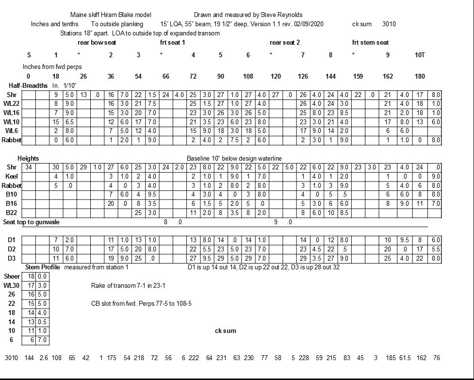
This is where the problem of lofting scale had to be addressed. The past two boats I have lofted were 20-footers, and I drew them up at 1/2 scale so I didn’t have to provide a 20+’ space, which was going to be difficult. On those boats, I drew a body plan full size – this took only a piece of plywood roughly 36″ x 44″ – measured the offsets on that plan and transferred to a spreadsheet, then divided all the measurements in half. The profile and half-breadth plans could be done on 10′ of plywood instead of 20′. This worked, but was cumbersome. On this new boat, I came up with the expedient of drawing in centimeters. Given two rules, a metric and an inch ruler, I could go back and forth with no conversion. The drawing comes out to be 40% the size of the full boat, or, about 6 feet for a 15′ boat, which I found manageable, and accurate enough for what I intended. I am presently done with the first round of fairing the lines. Below is the table of offsets.

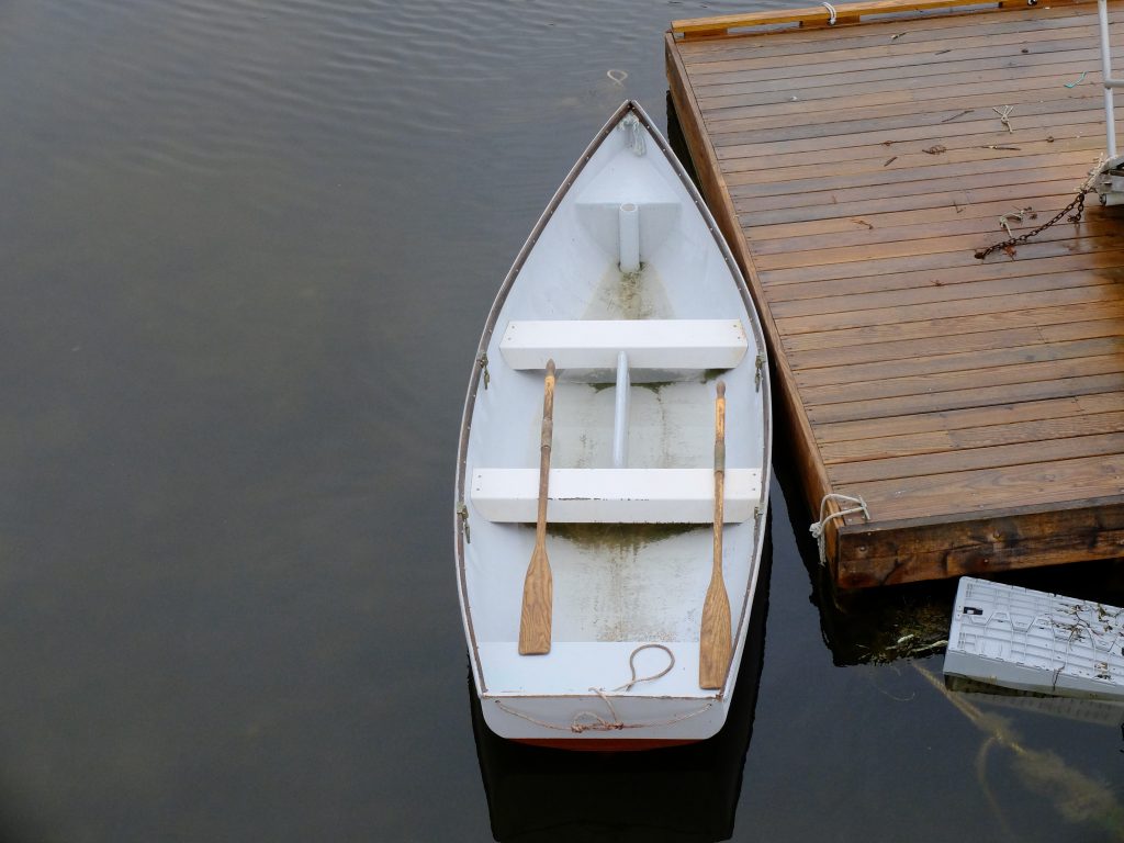
Here is an overhead view of one of the boats.

I think the next step is to make a half-model at a 1″-1′ scale.