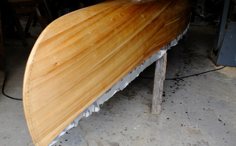
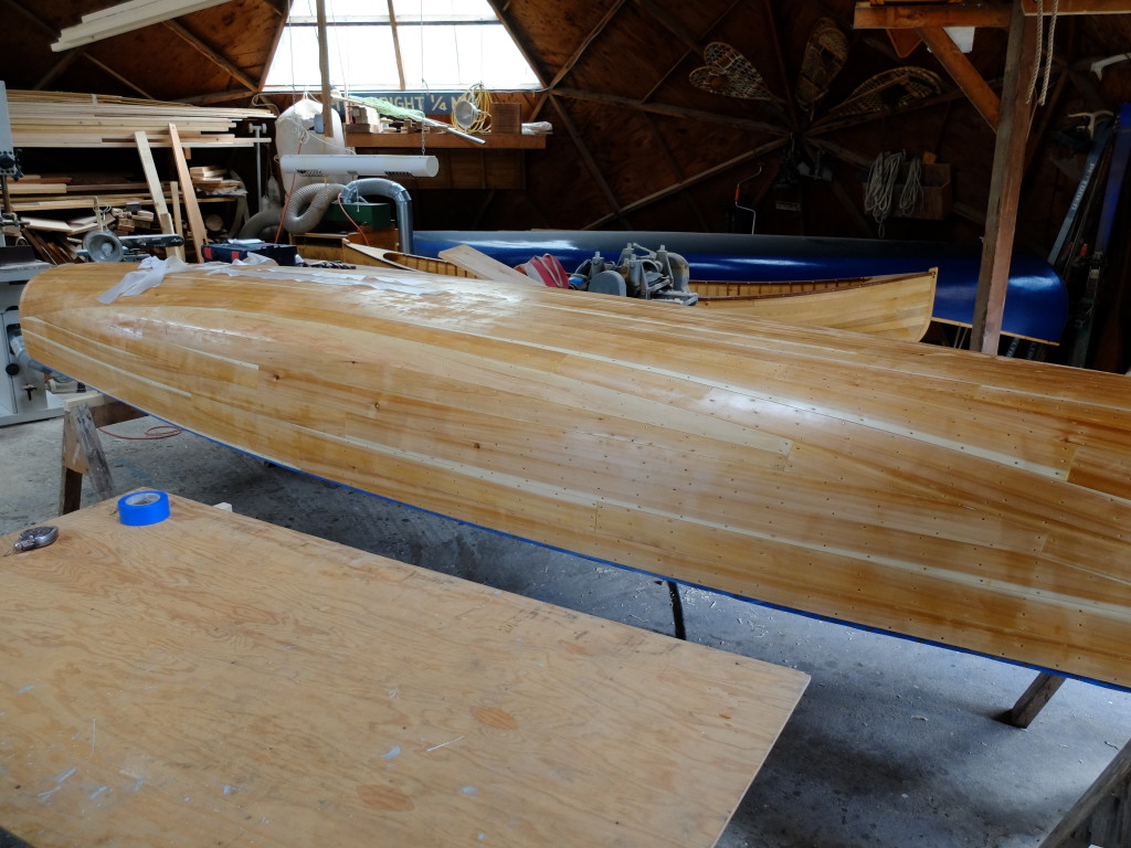
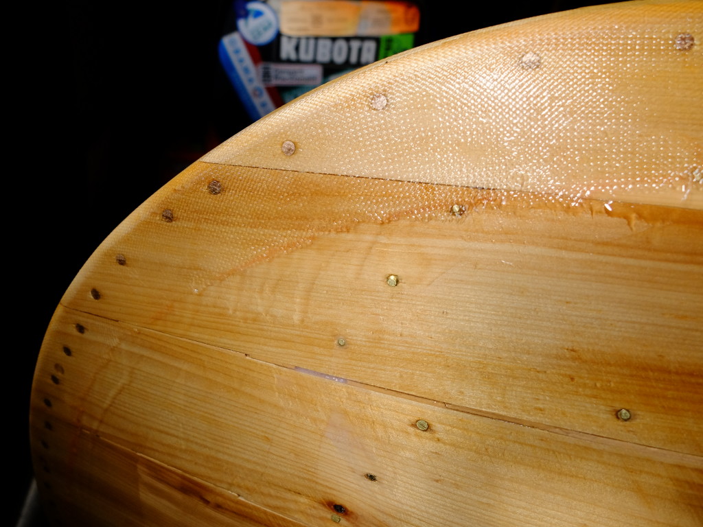
Grand Laker Canoe Hull Variations

There is only one published source of plans for a Grand Laker canoe that I know of, and that is in Gil Gilpatrick’s book ‘Building a Strip Canoe’.  When I decided I wanted to build a square stern canoe, I started looking for plans and considered Gil’s but changed my mind when I could not find pictures of boats built from his.  Instead, I drew up my own plans based on boats I measured.  I am still interested in how these boats vary one from the other, and decided to work Gil’s plans up by lofting them and developing a table of offsets, so I could understand where his boat fits in the evolution in shape that these boats went through from their origins in the 1920’s until now.  I hope I can add to the slim documentation of these iconic boats, and give his plans credit for documenting one phase of their development.  Gil has kindly given me permission to publish my results in my blog, for which I am grateful.

My first edition copy of ‘Building a Strip Canoe’ has plans for a Grand Laker at 1/3 scale.  The plans include outlines for 10 stations plus transom and stem profile, drawn to what would be the inside of a strip-built hull, but they do not include a table of offsets.  While the plans as-is can be used to construct a form, I saw several reasons to loft them.  Lofting would prove the fairness of the lines and allow me to measure any part of the boat I wanted.

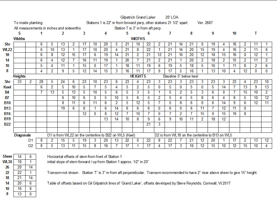
Starting with measurements taken directly from Gil’s drawings, I would have to develop a table of offsets in order to do the lofting, but I would also have to make some changes and assumptions about the boat.  Gil’s plans show each station through the boat at 20″ intervals along the length, in what would be called a ‘body plan’.  However, the stations are not lined up so that the keel appears straight, but lined up in reference to a line running approximately from the top of the stem to a point about 5″ over the transom, which becomes the plane of the form backbone once the stations are assembled for the form.  Thus, it is difficult to visualize the anticipated shape because the baseline is not parallel to the keel – making the boat appear ‘bow down’ in the plans.  I would want to establish a new baseline parallel to the keel.  Other minor problems included:   it is unclear whether the station labeled ‘stern’ is the expanded shape of the transom, or the transom as it appears viewed directly from astern; the sheer line height at station 1 is not indicated;  and, the space between each station cited in the plans, 20″, will yield a boat only 18′ 6″ (10 spaces plus 22″ stem projection) – whereas most Grand Lakers are 20′.  I would spread the stations to 21 1/2″ to yield a 20′ boat, and loft that.

I established the overall slope of Gil’s baseline perspective to be 5 5/8″ over 200″, and then calculated the amount of vertical adjustment at each station necessary to level his drawing – the adjustment got bigger with every station moving from the transom to the bow.   Taking measurements off his plans, I developed a table of full-sized vertical offsets at buttock lines spaced 3″, now corrected to a new baseline parallel to and 5″ below the keel.  (Buttock lines are vertical slices through the hull running lengthwise parallel to the keel, as opposed to waterlines, which are horizontal slices running through the hull parallel to the waterline.  The vertical lines below are buttock lines and the horizontal lines are water lines.)  I used the vertical offsets to draw a preliminary body plan full size – rough draft, below.  From this drawing I was able to measure horizontal offsets for my first stab at waterlines.
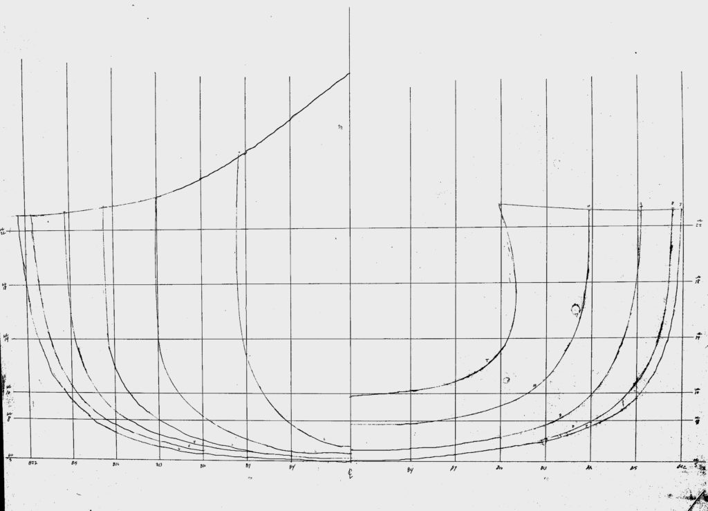
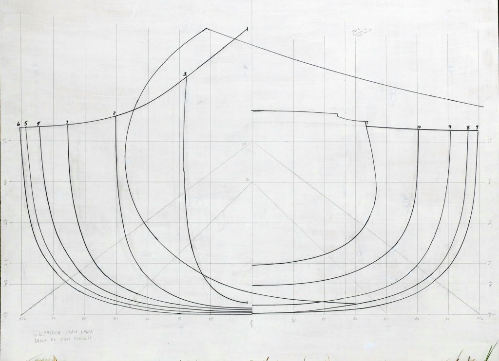
Referring to the above drawing – the baseline is 5″ below the keel for convenience of measuring.  Waterline ‘5’ is therefore at the level of the keel, the next one up is WL8, then WL10, 14, 18 and 22.  I chose these waterlines arbitrarily.  I am interested in the underwater shape of the hull, and waterlines 8 and 10 will give me that information when lofted.  The buttock lines proceed out from the vertical center line – the first is B4, and then they progress every 3″ out to 22″.  The front half of the boat is on the left, the aft on the right.

Several observations about this design can now be made.  The sides are nearly vertical in the forward third of the boat, with flare developing through the mid sections going to strong tumblehome only in the transom.    Maximum beam occurs at station 6, which is just aft of center.   The center section of the keel is nearly straight.  There is about 1″ of rocker forward of station 3 and marked tuck in the stern aft of station 8.  There is about 5″ to the tuck, going to a transom that is 13″ tall.  The sheer is practically flat the entire way from the transom to station 3, where it begins an increasingly sharp rise to the stem.  Maximum beam is about 45″ and maximum depth about 18″.  The sections are moderately flat through the bottom and broadly rounded at the turn of the bilge.

What boat is this?  Gil drew these line 25-30 years ago.  Now, he does not recall details of the boat that he copied except that it was probably 20′ long, and at some point the plans got changed to the 18′ 6″ length shown in his book.  Without going out and measuring existing boats, the heritage of Gil’s boat is unclear, but it bears a strong resemblance, at least from photographs, to some boats I have seen.  Here are some examples of variation in hull form.

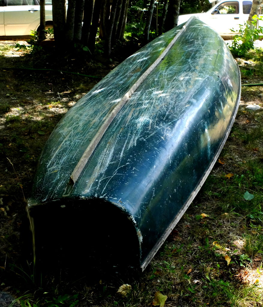
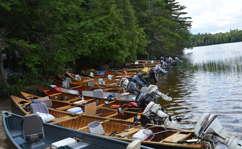
These boats were seen in western Maine.  Gil’s boat looks a lot like the one on the right.
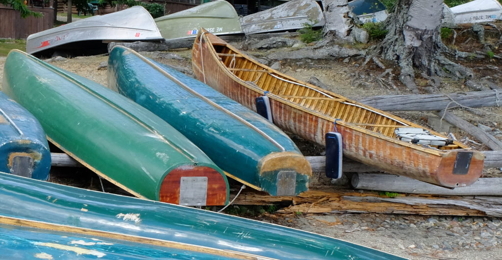
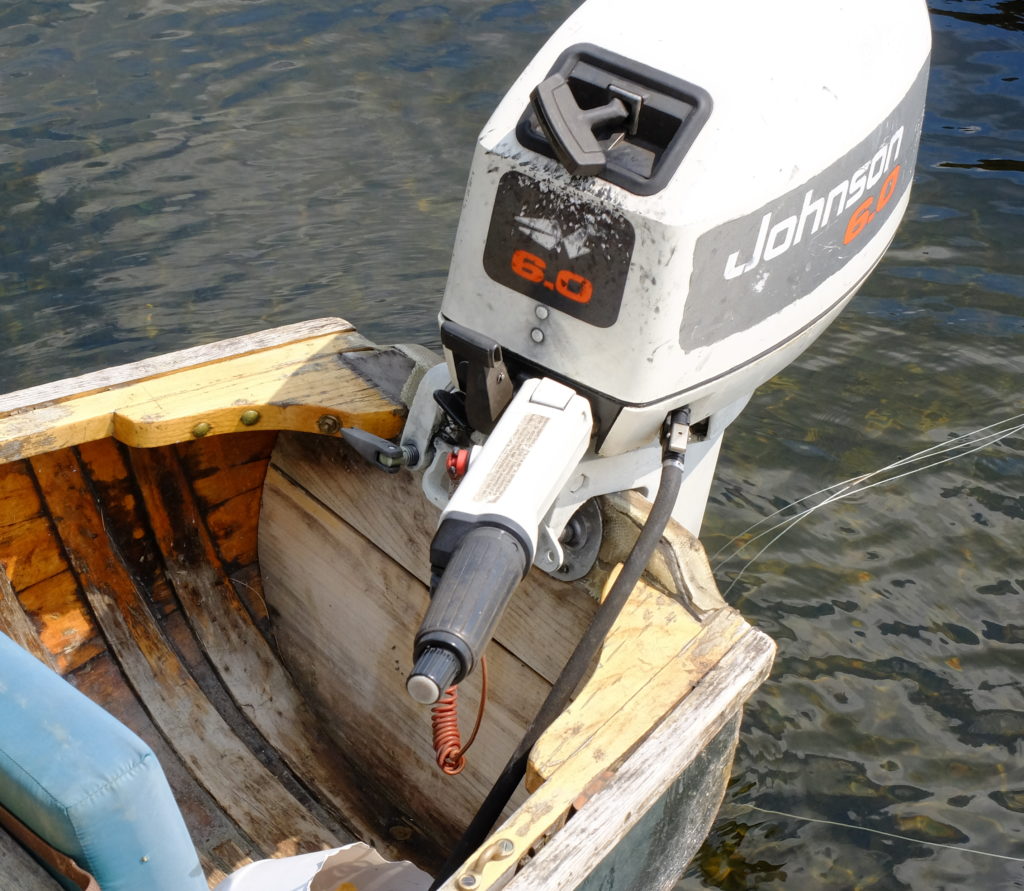
The middle boat is similar in the stern to the one on the right, but it is possibly flatter in the bottom than Gil’s.  The one on the left is a different model – more rounded body sections, fuller transom.  The 13″ transoms are raised above the sheerline by a riser to accommodate short shaft outboards that need at least a 15″ tall transom.  This is a close up of a transom of another these  boats showing the transom riser.  I will add a transom riser to the lines I draw from Gil’s plans.The western Maine boats in general show very flat sections.  This one, at the dock, and the one below it, by the Gate House.    I believe they were built from a form derived from a boat from Grand Lake Stream, and they seem to be mid-way in the evolution of the shape that started with a large canoe with the stern cut off, and the more recently built boats that are intended for larger motors.  The youngest of these boats is now 15 years old.  I believe they represent one branch of the Grand Laker family as it was some time ago.  Newer boats show larger transoms built on forms that were probably modified for that end.  This is a Pop Moore boat built in 2011 at Weatherby’s Lodge by Bill Shamels which shows almost no tuck in the stern, compared to boats built at Grand Lake Stream in the 1930’s.
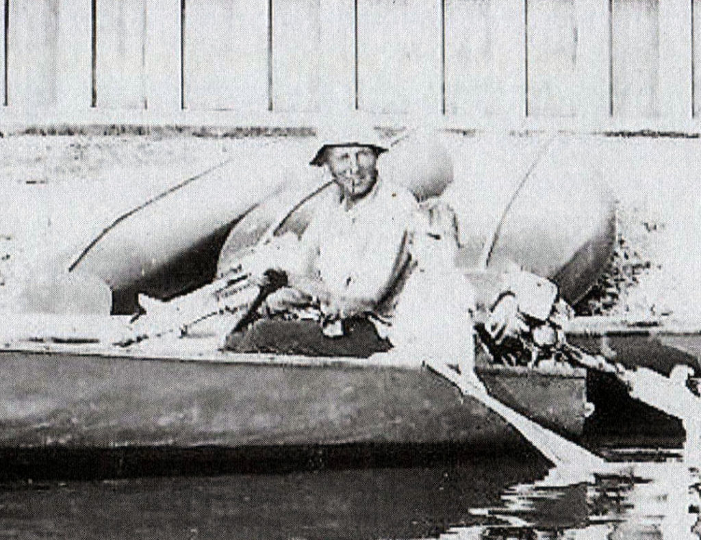
More recent boats like this one by Dale Tobey combine rounder and deeper mid sections, larger transoms and less pronounced tuck.
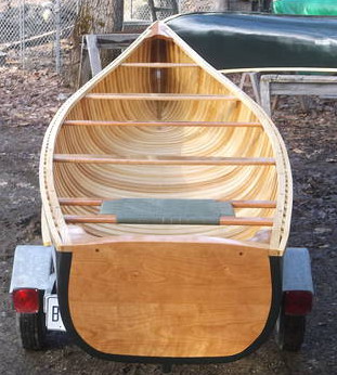
Finally, for comparison, I have mine (under construction).  A little flatter in the middle and sharper in the bow.
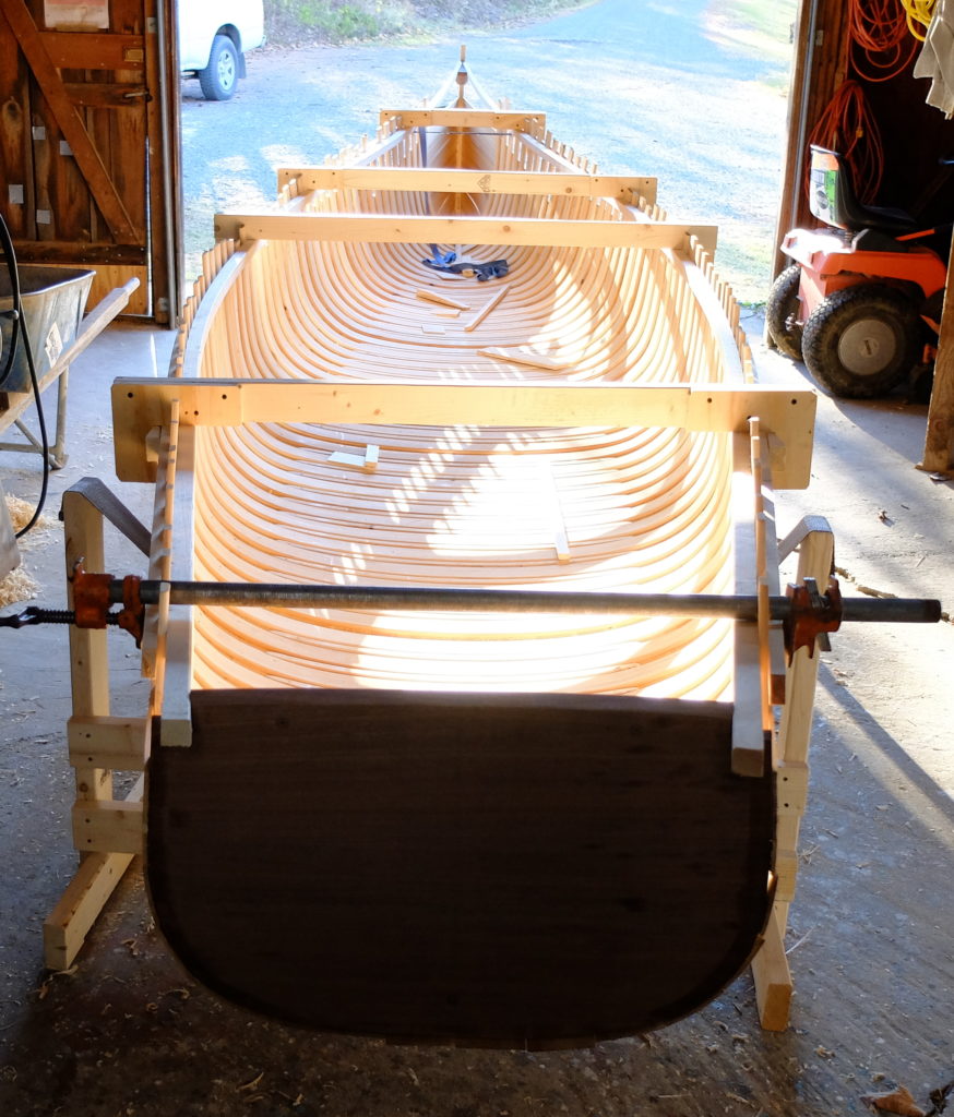
Lofting entails drawing out the shape of a boat full size, or at some appropriate fraction of full size, and connecting the stations with lines to prove that a smooth curve can be produced from one station to another along certain selected sections.  For instance, a line connecting all the stations where their outside surface hits waterline 8 should be a smooth line.  The purpose of lofting is to assure that a smooth hull can be produced, and also to provide a representation of the boat that can be used to measure other shapes.

Lofting produces three views of the boat – the body plan (as shown early in this blog entry), a profile or elevation plan, which is the boat viewed from the side, and the half-breadth plan, which is the boat viewed from above.   The drawing below includes all three views showing the lines of a square stern canoe I drew based on the western Maine boats.

During the process of lofting, decisions have to be made as the need for corrections arises.  In the case of Gil’s boat, I had to decide whether I was going to try to ‘improve’ the design as well as fair the lines, and I decided I wasn’t, except for length.  ‘Lakers’ are almost universally 20′ long or close to it, and I adjusted the spacing of the stations to accomplish that.  If I were to otherwise try to improve it, I would give it more sheer in the stern and more graceful sheer in the bow, less tuck and a higher transom.  In order to preserve the documentary value of his plan, I decided not to do that, and just fix what seemed like obvious errors.  Where I could not get things to line up smoothly, where the faired lines gave notably different measurements than I got off the plans, I worked with what seemed to be the majority of the points involved and adjusted the outliers.  This happened in the bow sections mainly.  I could not get the full bow to fair smoothly with the rest of the hull, and so sharpened it a little.  I placed the ‘stern’ station vertically, 3″ in from the aft perpendicular, and left it to the builder to determine the real shape of the transom, which is raked about 2″ in 15″.

I now have a table of offsets for the lines I drew from Gil’s plans –
and a body plan at full size, after lofting the profile and half-breadth plan at 1/3 size.  If you want to compare it to Gil’s plans, you’ll have to buy his book.
Tenor Uke

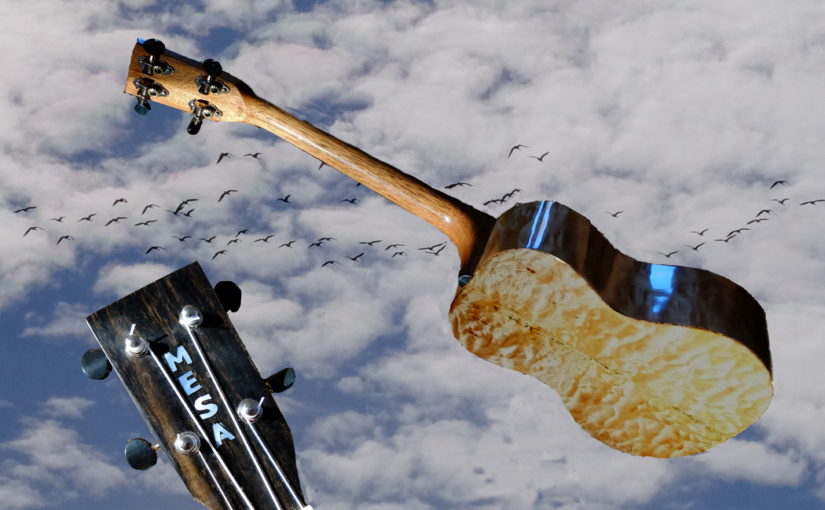
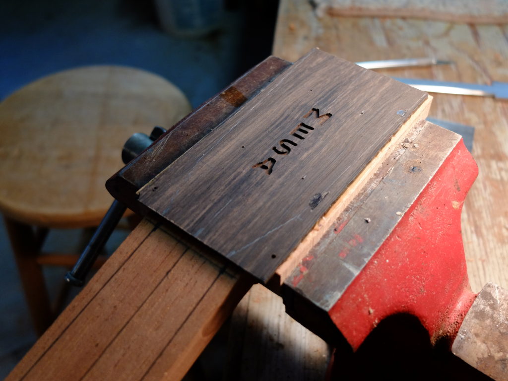
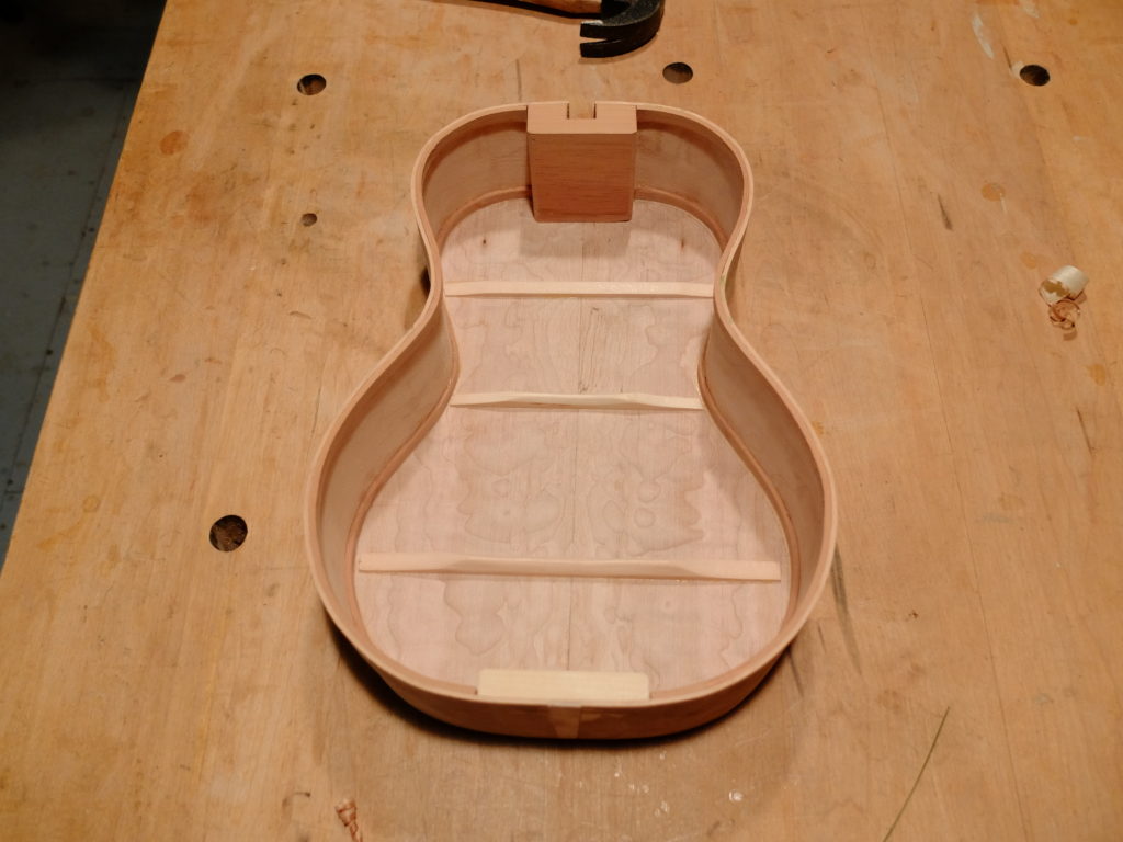
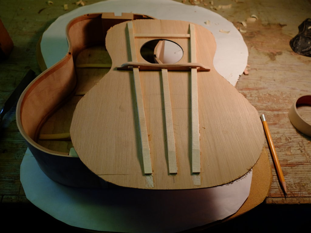
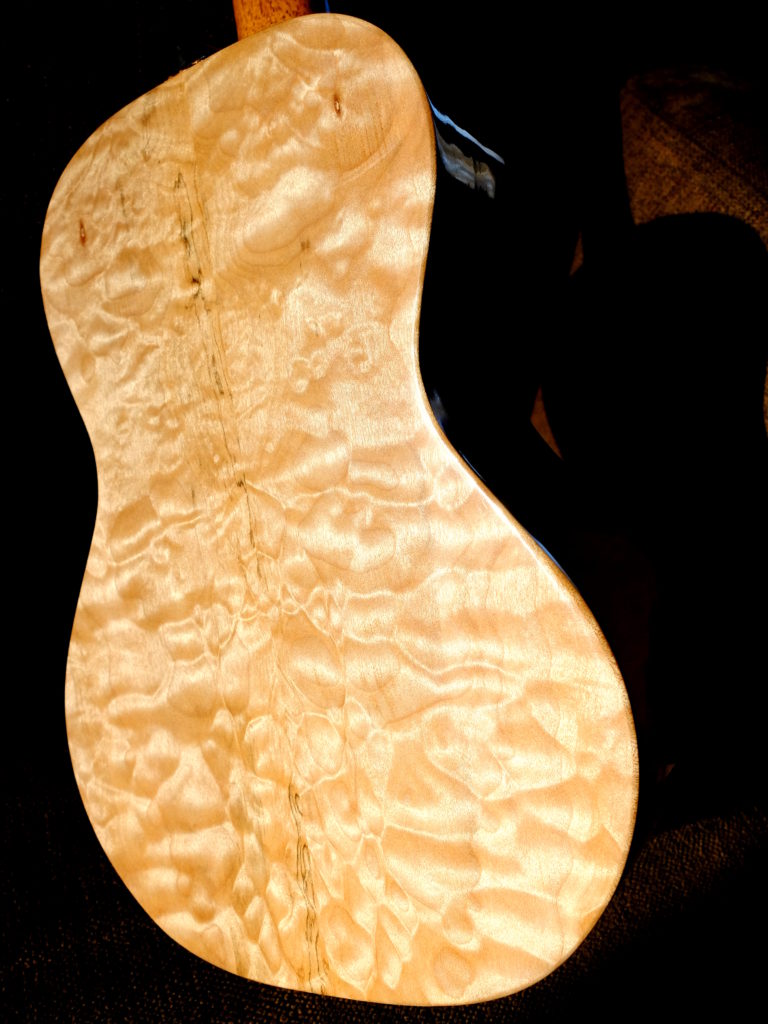
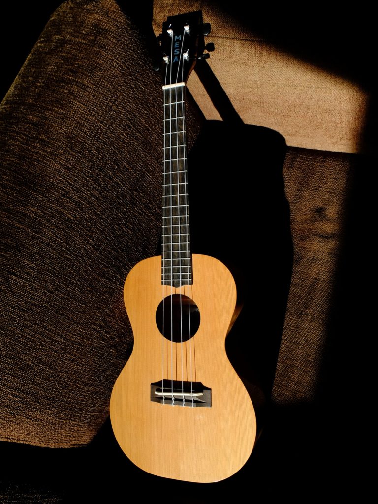
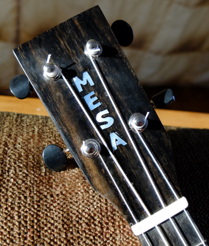
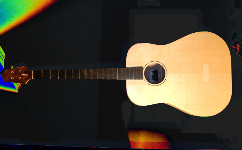
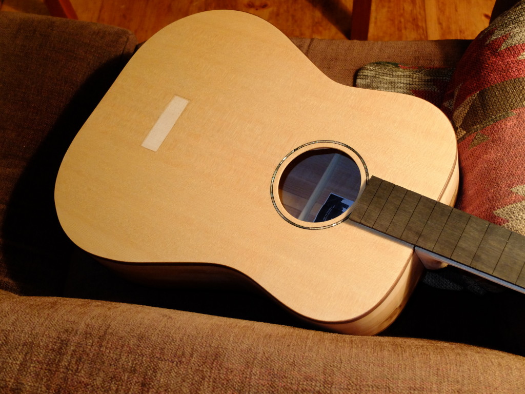
My grand daughter is showing signs of talent with guitar-family instruments, so I decided to make her a tenor uke for Christmas.  Back and sides are quilted big leaf maple, around 0.070″ thick.  Top is western red cedar, around 0.078″ thick, lightly braced, no bridge plate or anything like that.  Solid linings 0.080″ thick to minimize reduction of resonant area on the top.  Neck is spanish cedar, using a mortise and tenon neck joint, glued and bolted for good luck.  Peghead, fingerboard and bridge are certified sustainably harvested second-grade ebony, and her name is inlaid in pearl.  Peghead being readied for inlay – DSCF1513
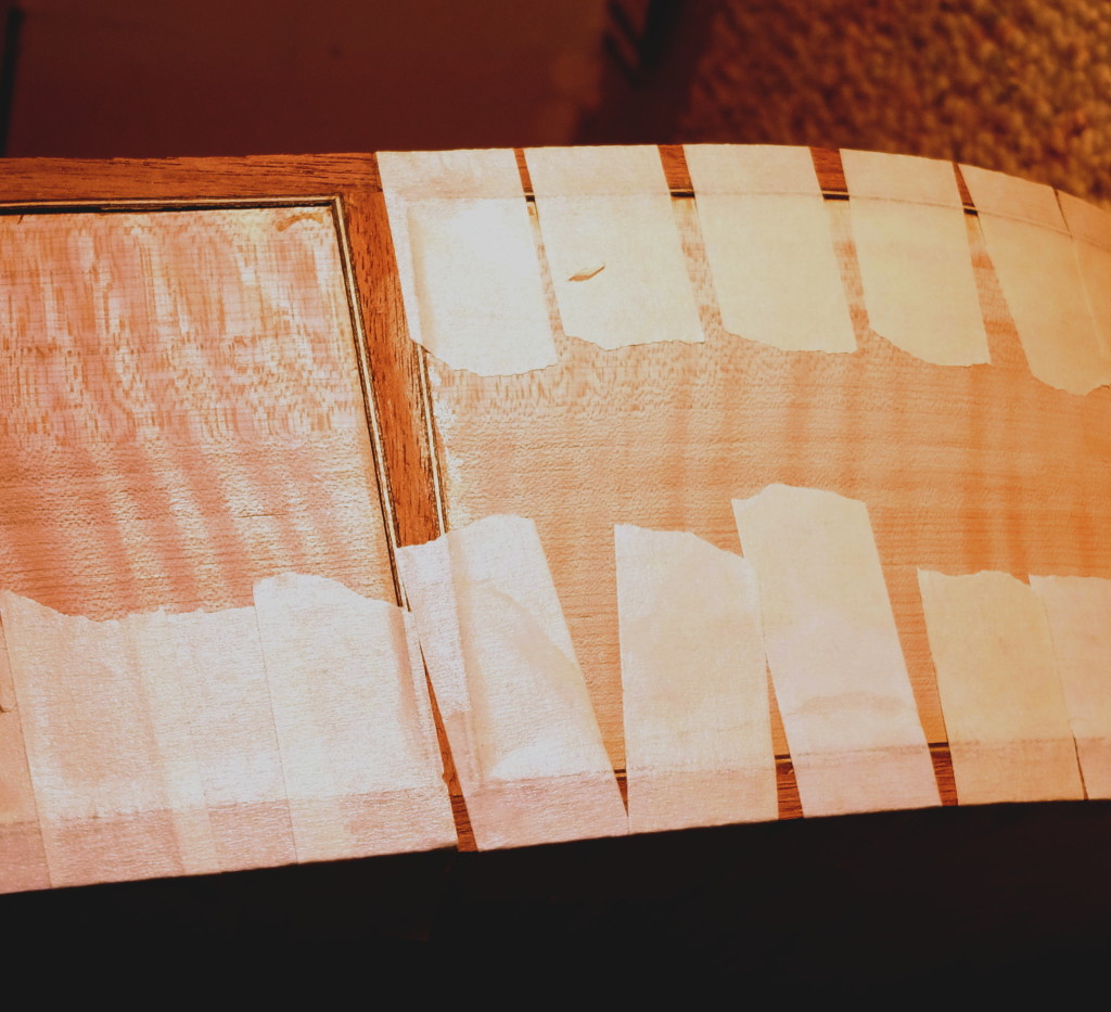
Back and sides ready for glue-up

DSCF1520

Top bracing complete – flat braces pass through cross brace without contact.

DSCF1522

Finish is 10 coats of Tru Oil hand rubbed, sanded between coats 5 and 10, and rubbed out with Meguiars buffing compounds – complete in 3 days (Christmas rush).

DSCF1573

DSCF1569

DSCF1571

I was excited to see her play it.


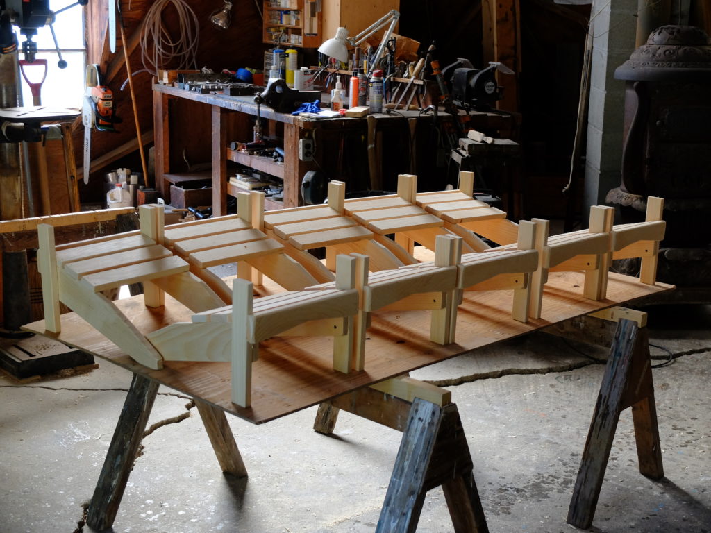
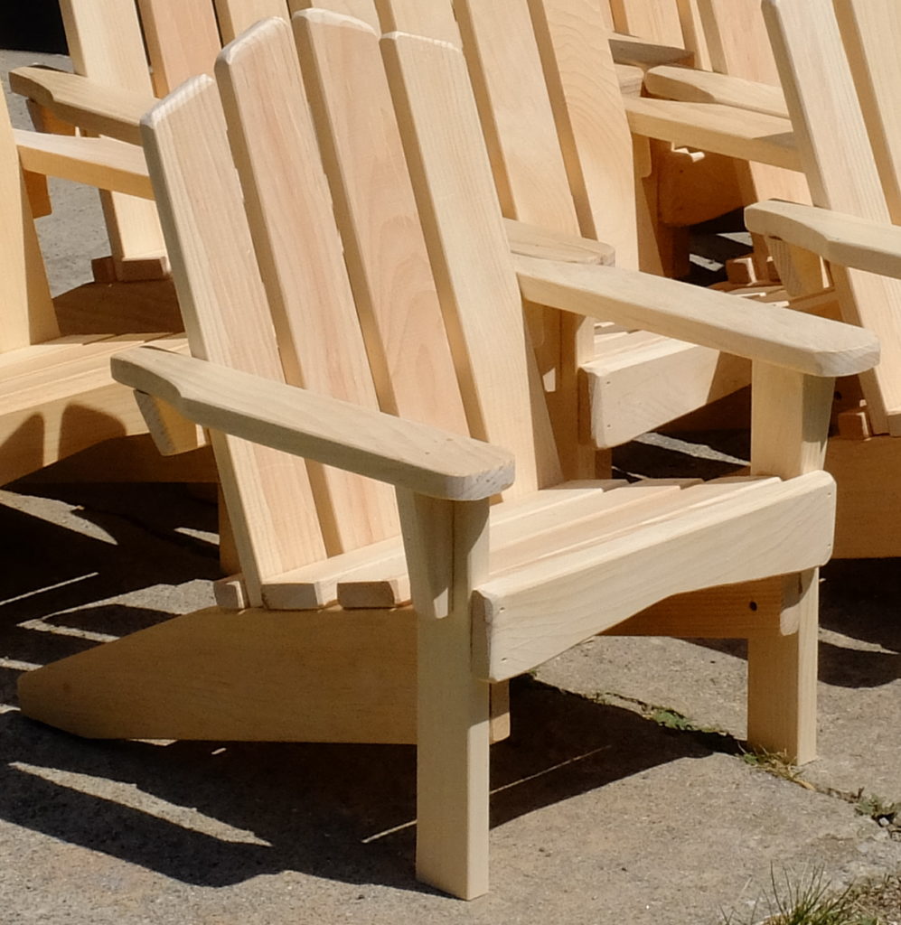
Child’s sized Adirondack Chairs

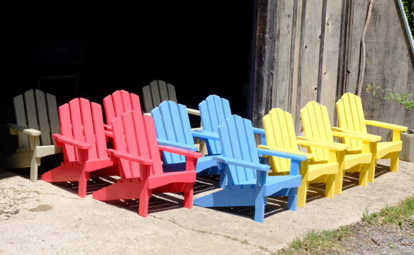
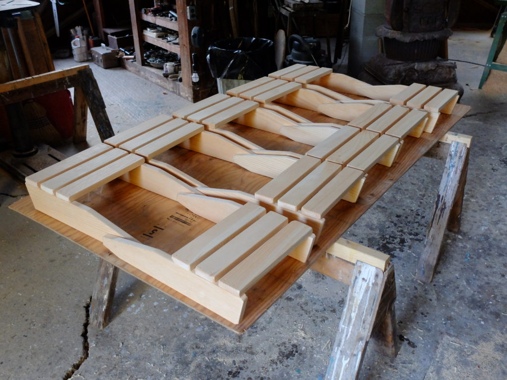
This is a summer project that looks good in January.  Pine chairs kids will love.  All made with 3/4″ (actual thickness) pine.  Start with 2 side pieces 3 3/4″ x 20″ beveled at front and back so back will sit on the ground, front elevated to 7 5/8″.  Cut 3 pieces for seat bottom 2 1/2″ x 12″, fasten to side pieces with 1/2″ space between, with back of seat 8 3/4″ in from the front.

DSCF1164

Cut 2 legs 1 7/8″ x 11 3/8″ and attach to outside sides, fastened from inside, so top of side piece is 7 5/8″ off the ground.  Cut and fasten 2 1/2″ x 13 3/8″ front apron so its top is flush with seat.

DSCF1166

Cut back pieces – 2 @ 2 1/2″ x 14 3/8″, 2 @ 2 1/2″ x 15 1/2″, and fasten them to middle back support (2″ x 14 7/8″) and lower back stop 1 1/8″ x 12″.  The top of the middle support is 6 1/2″ up from the back bottom.  Use a 9/16″ spacer for the back so the assembled back is 11 5/8″ wide.  Cut two arm rests 2 1/2″ x 14 1/2″.  Fasten lower back stop to sides and fasten arm rests so they overhang the front legs by 1 1/4″, and the projections of the middle back support by a like amount.  Bevel the ends of the middle back support where the arm rests attach.  Nail and glue all joints.   Paint as desired.

DSCF1167_a

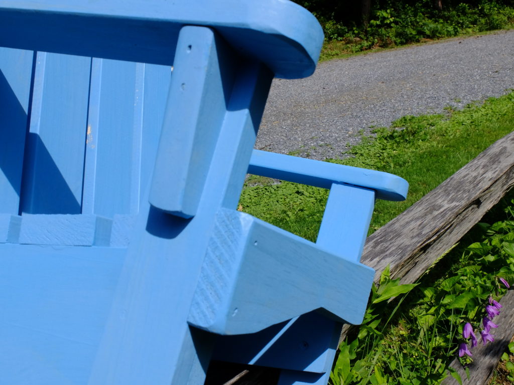
Add arm rest braces 1 3/8″ x 3 5/8″ as above and below (closeup of side view of arm rest brace, front apron, etc).

DSCF1190

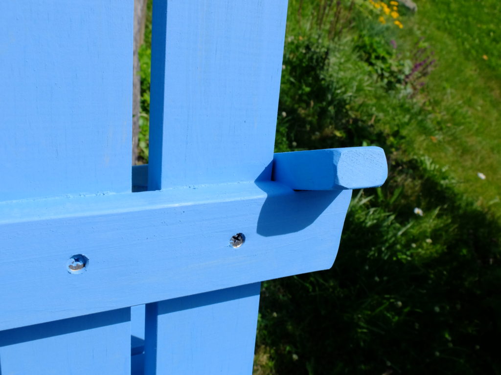
Closeup of back middle support piece showing overlap of arm rest and bevel of support.

DSCF1191

Fiberglassing a Grand Laker Type Canoe and Finishing Up

I spent many more hours planning the fiberglassing step than it takes to actually do the work.  Handling the epoxy/fiberglass can be tricky and the consequences of messing up are serious in several ways.  The materials and methods I used were gleaned from advice and books and on-line videos, and none of the steps I took were either pushing the limits of the materials or outright experimental.

Materials used :

  • 30 yards 6 oz. x 42″ fiberglass cloth, shipped in a roll (not folded)
  • System Three Silvertip epoxy, 2 gallons resin, 1 gallon slow hardener (actually used 2 1/3 gallons), with metering pumps
  • ACE hardware wood filler
  • WEST 407 filler, 1 can
  • WEST 800 rollers – used 6; disposable roller pans and roller frames
  • two or three 6″ squeegees
  • dozen 3″ chip brushes
  • mixing containers (quart yogurt cans) and grunge cups (12 oz. paper coffee cups)
  • half a sleeve of good quality 120 grit sandpaper
  • quart Pettit EZ Prime 6149 topside primer
  • two quarts (750 ml) Epifanes Yacht Enamel, applied with high density foam rollers
  • three quarts Interlux Schooner Varnish #96

For sources, I relied on Ted Moores’ book Canoecraft, on Epoxy Basics by Russell Brown, on-line videos by Nick Schade, and advice from Jerry Stelmok, Paul Labrie and Dale Tobey.

Starting with the bare hull, Jerry advised  me to used a filler to plug any holes/spaces in the bottom that would let epoxy drip into the inside because the water-thin epoxy will make a real mess if it runs through the cracks and makes icicles inside.  He suggested Ace Hardware 18932 water-based filler, which handles a lot like Durham’s Water Putty, but without the need to mix it.  The filler itself has little strength – you just want it to stay put until the bottom is sealed from inside and out.   I went over the outside of the bottom and filled any voids, then gave the inside of the boat a couple varnish coats to lock the filler on the inside.  This would not work on a boat without tight planking – a lot of filler would be forced inside making a mess.   With the boat bottom-side up, I then faired and sanded the outside, and rounded the edges of the transom and stem.

The System Three Silvertip epoxy with the slow hardener has a long working time, sands cleanly, can go up to 72 hours between coats and still get a chemical bond, is low viscosity specially formulated for laminating, has a wide temperature curing range, is tolerant of a wide humidity range, and has no amine blush.  The only downside is the cost – it is twice as much as some other epoxies.  It takes about 2 1/2 gallons (resin and hardener combined) to layup and coat the two layers of 6 oz. fiberglass 40″ wide, lapped 2″ at the keel.   I got my glass from Raka; don’t get it folded – have it shipped rolled and be sure it is compatible with epoxy.  For applicators, I used 6″ squeegees, 7″ rollers from WEST (part #800), and 3″ bristle chip brushes.

Once the boat was sanded fair, the bottom was given a single sealer coat of epoxy to prevent the first layer of glass from getting resin-starved, applied with a roller. My shop this time of year (early May) runs up to 70 degrees during the day and dips down into the low 40’s at night – but the Silvertip had no problem with an  overnight setup.  Warming the resin and hardener before mixing by keeping the containers in buckets of warm water helps.

DSCF1077

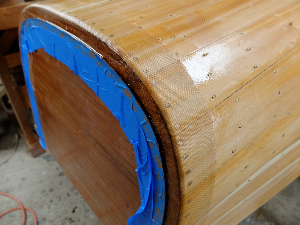
I found it easy to handle the places where the 6 oz. fiberglass would have to bend around the transom and the stem, having taken the precaution to round over the sharp edges.   My transom has a recess cut around the periphery to receive the fiberglass.  The first layer at the bow and stern, was a piece of 4″ bias-cut tape.  This went on cleanly, and the next two full layers of cloth were just wrapped around as I went.  Below is the transom with the first piece of tape in place – used a brush to apply the resin and work the glass around the corner.

DSCF1076

Tape on the stem – you can see a little of the Ace filler.  It would have helped to go back over this with a squeegee to clean up the drips.

DSCF1079

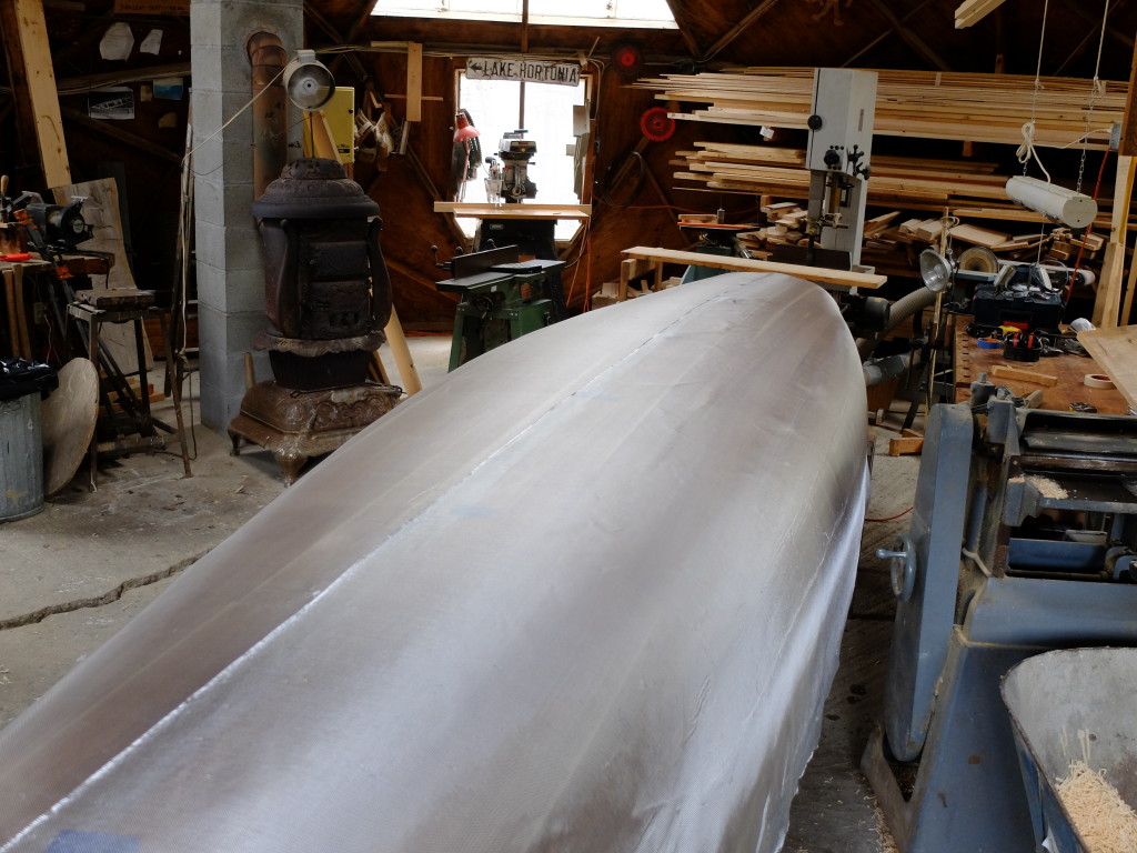
The cloth, unrolled and smoothed to the hull, ready for epoxy.  Use a dry brush to smooth out the wrinkles, not you hands.  The first layer (on the left, below) is temporarily held down the keel line with tabs of blue tape which got removed after the layer on the right was positioned.

DSCF1080

Following Nick Schade’s technique, epoxy batches were mixed and poured on, then spread with a squeegee.  After they started to slowly kick, which was about 1 1/2 hours later for me, the excess was squeegeed out.  See Nick Schade’s videos or Ted Moores for a description of this process.  The result of the first coat :

DSCF1082

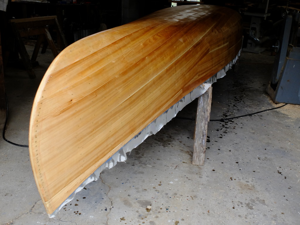
The second layer of epoxy went on the same, after trimming off the excess cloth at the gunwale from the first layer and giving the hull a light sanding to remove any nibs.  The first filler coat (first of two) went on with a roller, again after a light sanding, and then was tipped off with a dry brush to take care of most of the little bubbles left by the roller.

Several components of this system are toxic and have potentially serious health consequences including allergic dermatitis, respiratory and nervous system disorders.  Not all of the risks are obvious, the fumes generated during the curing of the epoxy being one example of a non-obvious hazard.  Never allow liquid epoxy in either mixed or unmixed components to touch any part of your skin.  Don’t breath epoxy sanding dust, especially in the uncured state, which can be for a period up to a week after applying it, and don’t breath the epoxy fumes, unmixed, but especially mixed and uncured.  I have had no adverse side effects from the Silvertip epoxy, but I am using lots of nitrile gloves, taking care to keep my shop clothes in the shop, washing with waterless handcleaner, and wearing a well-fitting 3M respirator with both an organic-chemical multi-gas cartridge and particulate pre-filters.  A beard will prevent an effective seal for the respirator. Continuously check the seal on the respirator – if you can smell anything, it is not working.

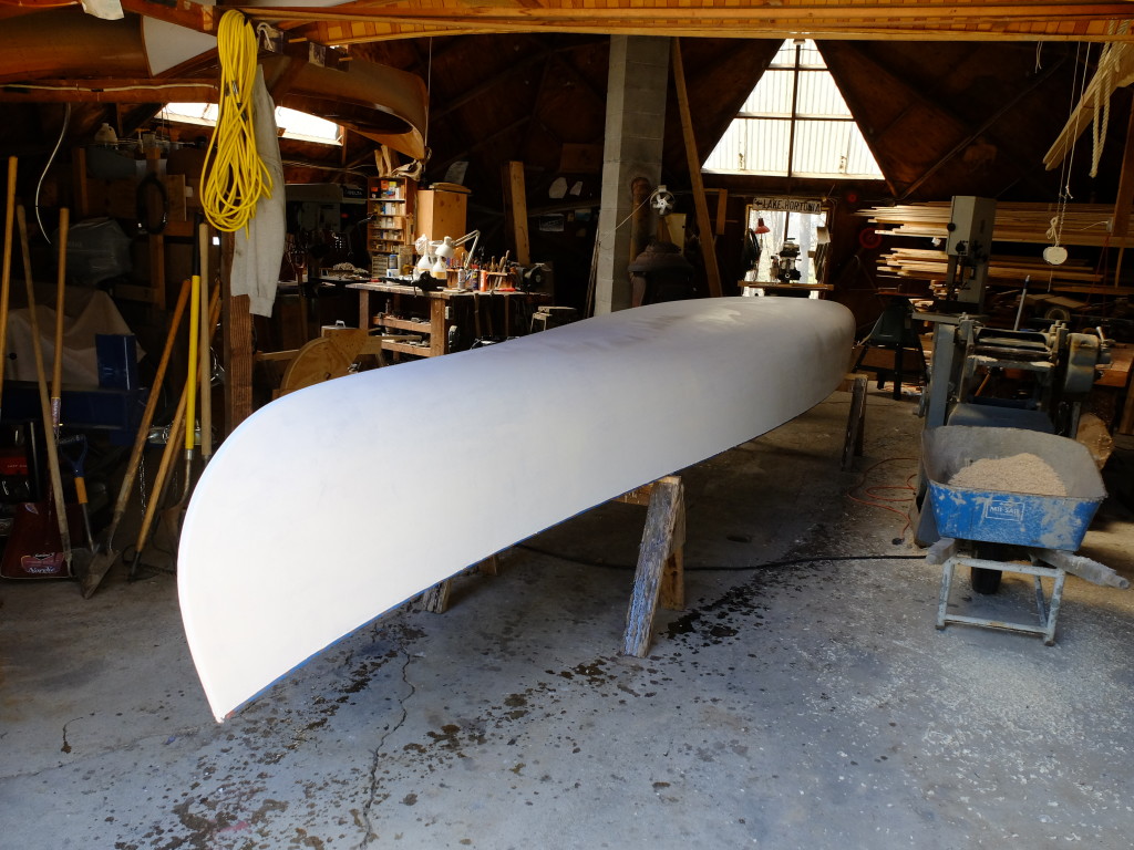
The second filler coat was thickened with WEST 407 low density filler, applied with a squeegee, to help control sagging of the epoxy on the many vertical faces of this boat.  After letting this coat set for a couple days, I faired the filler and rolled on a coat of the Pettit EZPrime, a high-solids primer that sands easily.

DSCF1094

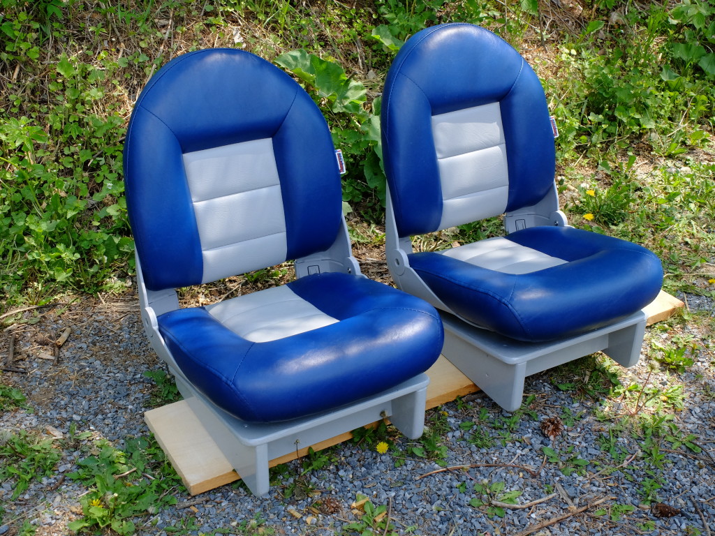
I used a skid-plate style keel made from 3/4″ white oak that narrows to 1″ wide at the stem and widens to about 3 1/2″ in the middle ending up around 2″ at the transom.  This was fastened every other rib from the inside with stainless screws.  The outside stem was bent on a form from white ash, scarfed into the keel piece, covered on its face by half-round brass stock fastened with #4 x 5/8″ screws.  The brass band was carried about 3′ back along the bottom of the keel.   Finish paint was Epifanes Yacht Enamel which I liked very much – dried hard and quickly with very little tendency to run when applied with a high density foam roller.  Two coats, each one thinned a little with Epifanes brushing liquid.   The seats are Empress Navistyle highbacks, mounted on wooden bases that let me move them around.

DSCF1103

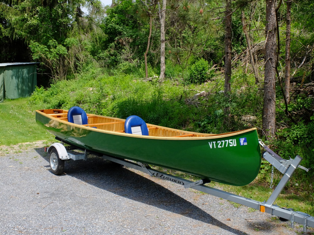
Fitted to the trailer and ready for first launch.

DSCF1106

Registering a Homemade Grand Laker Canoe

I did not give much thought to registering my new boat while I was building it, but I was aware that it could be a process because a friend of mine had built a boat from trees he felled and sawed out only to find that he had to pay sales tax when he went to register the boat, and he had to get a Hull ID number from the Coast Guard, which took him 4 months.  I went so far during the building phase as to burn a ‘serial number’ on the inside of the stem, naively thinking that would be sufficient for the box on the form labeled ‘VIN’.  I called mine ‘#01’.  Sort of a joke on them, bureaucracy.  Turns out, they don’t have much of a sense of humor.  Different states have different rules, and I played with the idea of registering it in Maine (I live in Vermont) because that is where I will use it, mostly, but also because it looked a little cheaper and I wanted the cachet of a Maine number on my boat, since that is its heritage.  The kicker is in the Hull ID Number.

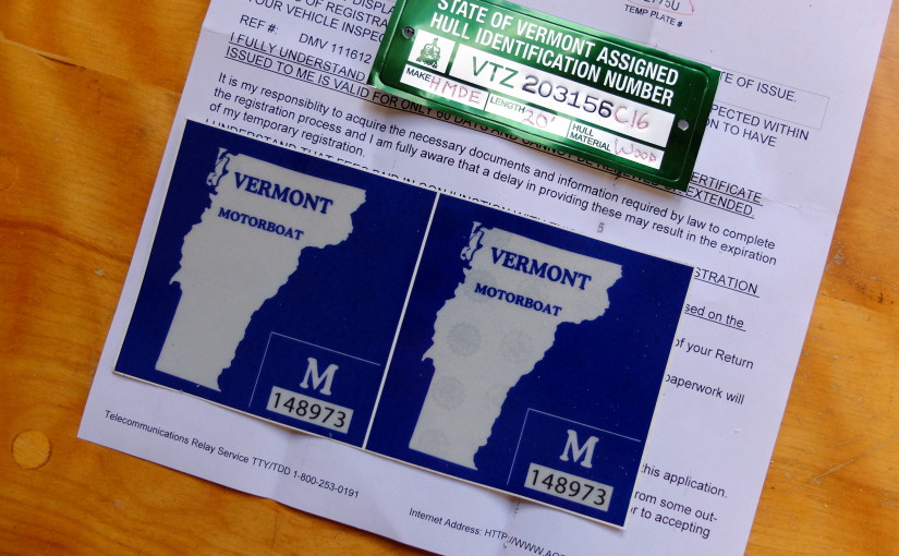
Briefly, every recreational motorboat needs a Hull ID Number (also called Vehicle ID Number: VIN) to be registered.  You also need to pay some kind of sales tax, as if you had bought the boat; you need a registration and boat numbers, and you may need to apply for a certificate of origin and/or title.  The application forms for the Hull ID Number state that an inspector from the DMV or applicable organization will come to your location and personally apply the ID plate, this to prevent fraud I guess.  In fact, when I went to try my luck today at the local Vermont DMV branch, the agent gave me the Hull tag to apply myself.  I don’t know if they would have done that through the mail, and I don’t know how Maine would have handled it.  Now that I have a hull ID number, it should be no problem to register the boat in Maine when I decide to keep it there.

The ‘sales tax’ is a little odd in that I either already had paid sales tax for the materials used, or made a general ‘use tax’ payment at income tax time which is designed to collect the tax due on out-of-state / internet purchases.  The Vermont form ‘Application for VIN’ says that the form will be rejected if a bill of sale is not included for ‘any and all parts’ used in the assembly.  Based on the fact that I had no such bills of sale, I was not in a position to argue with the DMV clerk.  I lieu of bills of sale, I made up a semi-complete materials list – so many board feet of white cedar, 3 pounds of tacks, etc. – and included copies of either canceled checks or credit card statements.  Some materials I had not bought yet, like the epoxy and fiberglass cloth, but put together a shopping cart of my intended purchases and included a print-screen of that.  This list was accepted, and the sum total was used as the taxable price.  The DMV subtracted from the tax due any tax I could prove I had paid, like on the motor, and this is the advantage of actually keeping receipts, if you want to trouble yourself to that extent.

I ended up preparing 4 forms, plus my materials list.  The 4 forms were the VIN Assignment form, a Manufacturers Statement of Origin form, a Use Tax form, and a Motorboat Registration form.  It was a little like playing poker with the DMV agent – he held all the high cards and he didn’t divulge a lot of his thinking.  I paid $160.54 which breaks down to $43 for a 1-year registration, $97.54 tax on my materials, plus $20 for something that he didn’t tell me, but I hope is a title – that’s what a title costs, although one form says canoes over 16 feet with motors less than 10 HP don’t need a title.  I will wait and see – just like Christmas.

I didn’t like the ‘Make’ and ‘Model’ names he chose – my Make is “HMDE” and Model “MBT” – my choice for Make was “GLT” for Grand Laker Type, and Model was simply “Grand”, but you can’t have everything.

Acoustic Bass

A friend who has one of my short-scale electric basses asked me to build him one that he could play acoustically – which became this project.  There are several acoustic basses being made that I used to get ideas from.  Among the most successfully demonstrated is this Olav Loef guitar played by Martin Tallstrom –  Also, a German builder named Christian Stoll builds some good sounding basses –

A Stoll bass appears at 4:32 in the clip below, followed by an Esteve PS 75 –
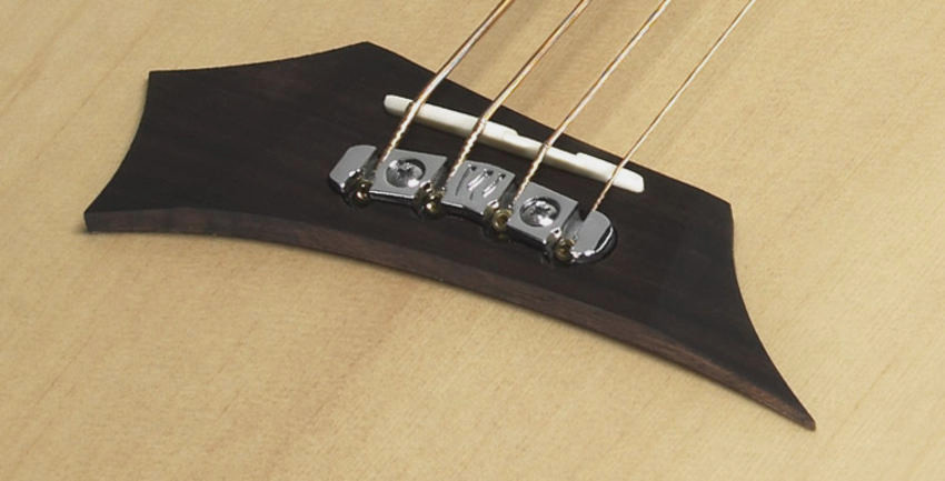
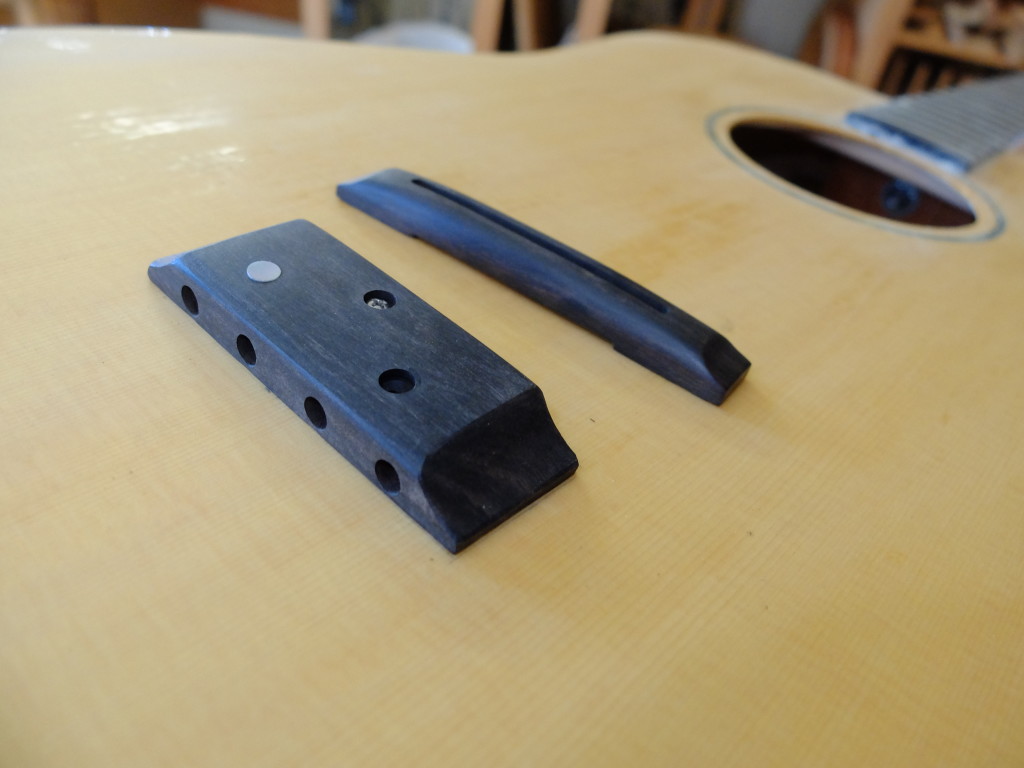
I compiled some comparison specs for different instruments – appearance of this guitar was important, so odd shapes/sizes/soundhole configurations were ruled outUntitledWe settled on a dreadnought-guitar-sized body, 30″ scale with 15 frets to the body, and a face-mounted ebony tailpiece with a separate floating bridge/saddle.  There are a few acoustic basses that use such a tailpiece/saddle configuration – like the Stoll – with a floating bridge, and a tailpiece that is both glued and through-bolted to the top – Stoll bridge Warwick uses a combined tailpiece/bridge –
WarwickA

While many good-sounding basses use flat-top steel-string style bridges with bridge pins, that approach doesn’t make a lot of sense to me because of the size of the strings, making that sharp bend, but more importantly to my thinking is the ability to adjust intonation after the fact of installing the bridge.  Basses tend to have a lot of angle to the saddle for intonation, and the amount depends also on the kind of strings used.  There are bases that use nylon strings as for classical guitar, like the Hannabach strings, and these need much less compensation for intonation than steel strings, like I intend to use (we are going to use Pyramid Gold flat wound strings).  The headstock design was based on keeping a minimalist size while giving a straight pull on the strings to the posts.   My customer wanted Fender-style knobs, and only Hipshot ultralites would allow us to use this small design, and had the right knobs.

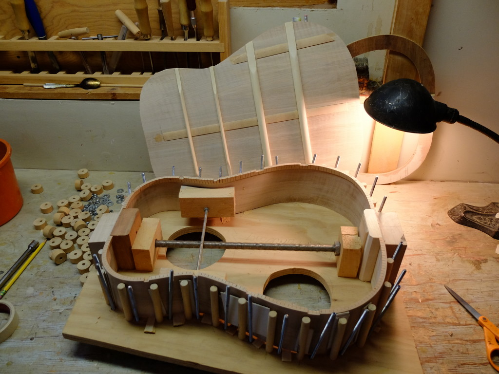
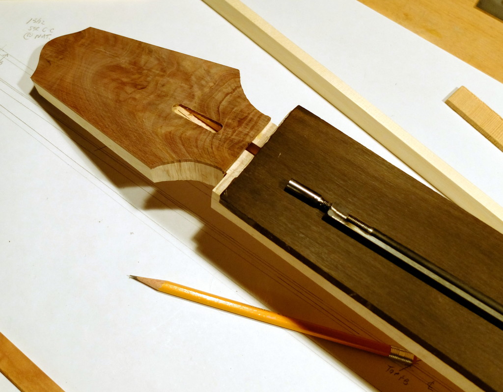
The back and sides are flamed swamp maple, neck block mahogany, tailblock spruce, linings are cherry.  I am using a 4-sided, mortise and tenon bolt-on neck joint.  The mortise/tenon is tapered on all 4 sides and makes a snug contact fit.  The bolts are hanger bolts threaded into the heel of the neck with the nuts and washers inside the guitar body.  It was a 4-piece back.  Below, sides are in the gluing form, back ready to be glued on.DSCF0915This is the neck in early carving phase.  Two-way truss rod, ebony fingerboard, burly black walnut headstock veneer, curly maple neck.DSCF0922

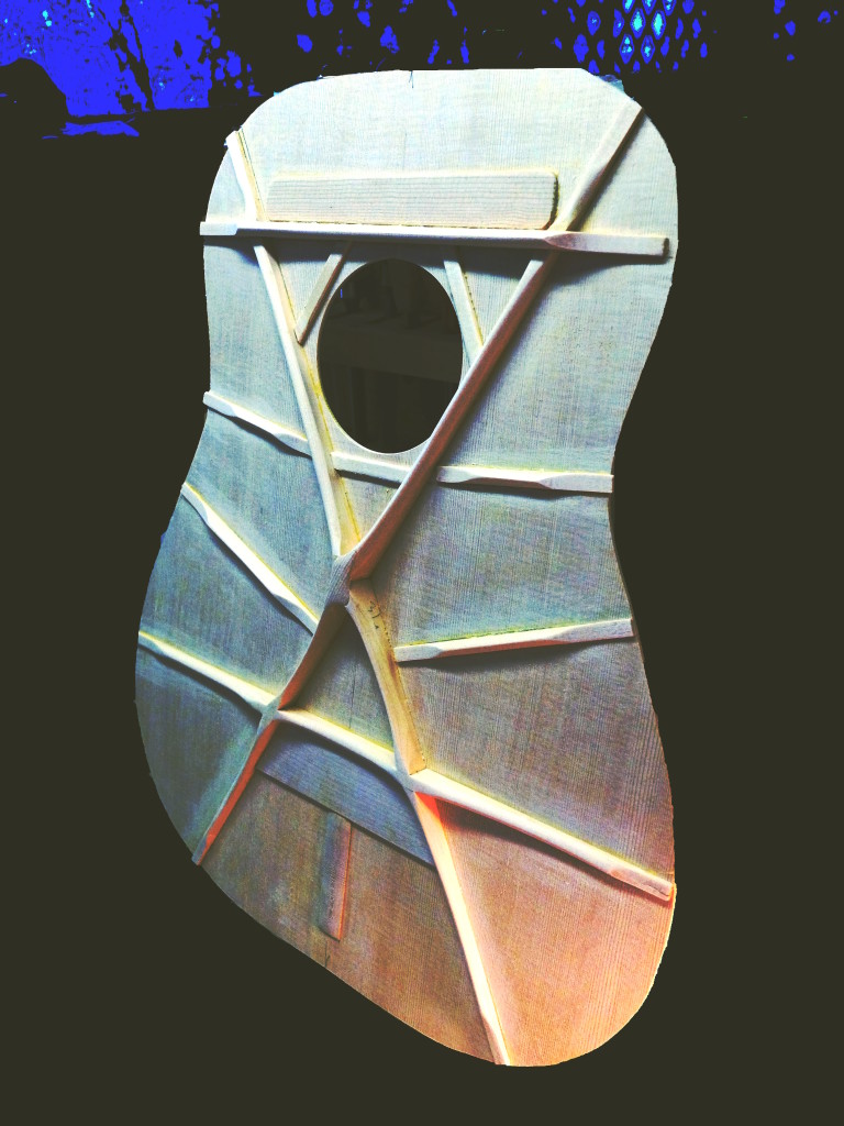
Contrast-enhanced picture of the top bracing.  This is a modified X pattern designed to distribute the tension of the strings with the almost direct forward pull on the tailpiece while supporting the bridge.  The top is Sitka spruce thicknessed to 0.110″, main braces 5/16″ x 3/4″ before carving.  There is a maple plate under the tailpiece location, and the tailpiece will be glued/bolted to the top.  The bridge will probably be kind of like an archtop bridge but without the adjustment posts, but have 2 feet that rest above the lower arms of the X.  We’ll see!DSCF0924Binding is black walnut with a black/white/black purfling.DSCF0926The guitar is in the finishing stages now and will be ready to string up in about 4 weeks.  (tailpiece location shown on top, below).DSCF0931Tailpiece / bridge setup – fixed tailpiece, floating bridge (saddle not made yet)

DSCF0979A note on strings – Usable string length is limited on basses to the length of the full-size wrap, which should be long enough to span the distance from the tailpiece to the far side of the nut plus some, but not so long that it reaches to the string post.  This means there is somewhat less than 2″ of leeway between a string which is too short and one which is too long.  On this bass, which has a 30″ scale, some brands of ‘short scale’ strings fit (Pyramid Golds being one), and some ‘medium scale’ strings also fit (Fender phosphor bronze), while some other ‘short scale’ strings were too short, and some ‘medium scale’ strings were too long.  I also found that not all string-end balls are the same size – some are quite a bit bigger than the ones on the Pyramid Golds, for example.  I did not anticipate this problem and will make adjustments to the tailpiece in future versions of this guitar specifically to allow certain strings to be used.

Intermission for a shed , then back to it

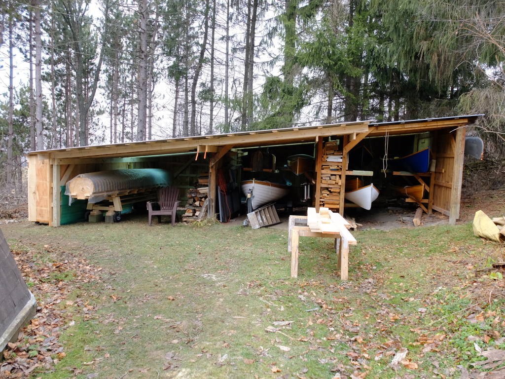
I knew I would have a storage problem with this boat, and took a couple weeks to add on to my boat shed to make a place to keep the form and the finished boat.

DSCF0863The two bays on the right were the existing shed – I still had enough headroom to continue the roof downhill another 12′ for the addition.  Boat count : 3 guideboats, 2 Rushton-design solo canoes, a whitehall, a Winona and a Grumman.  Plus 2 guideboats, 3 canoes and the new Big Guy in the garage.  I need to talk to my marketing rep.

I thought winter was coming and rushed to get the shed done and put up some firewood, but it is still mild here (December 13).  I was able to resume working on the boat this weekend.

There were 5 half-ribs to put in the locations where the form backbone bolted on, plus 4 pairs of cant ribs in the bow.  The cant ribs get thinner as they approach the bow so that the planking will lie flush at the stem.  They go from full 3/8″ to 3/16″ closest to the stem.  I upgraded my steamer burner to a 54,000 BTU King Kooker outdoor cooker made for Cajun-style cooking – what a difference.  It blew the lid off my kettle in 5 minutes.  It takes a helper to clench the tacks on the bottom of the boat – or, an orangutan.

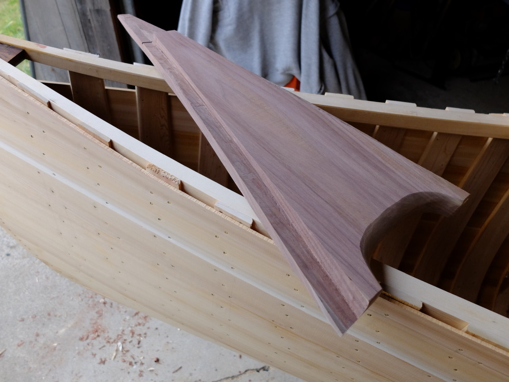
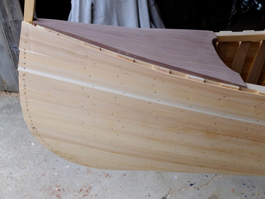
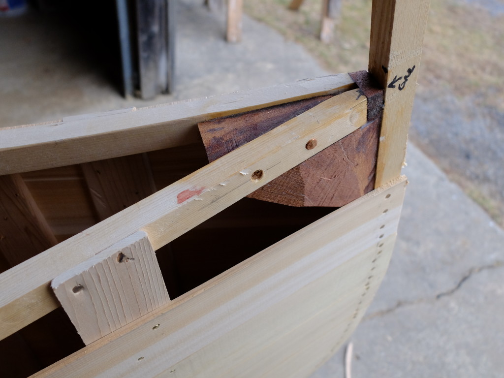
My method of joining the stem and inner gunwales uses a chunky mahogany block as a knee, screwed to the stem and through-fastened gunwale-to-gunwale.  The projecting top of the stem gets cut off later.  The last of the cant ribs is visible.DSCF0871The 4 pairs of cant ribs – DSCF0870The deck is made from a solid piece of black walnut.  I know black walnut is supposed to be bad luck in boats, but I don’t care.  I have some nice walnut my brother-in-law Fitzie traded me, and I use it when I can.  Besides, mahogany is way too expensive and scarce.  I cut the underside of the deck to capture the edges of the gunwales and cover the knee at the stem –DSCF0869

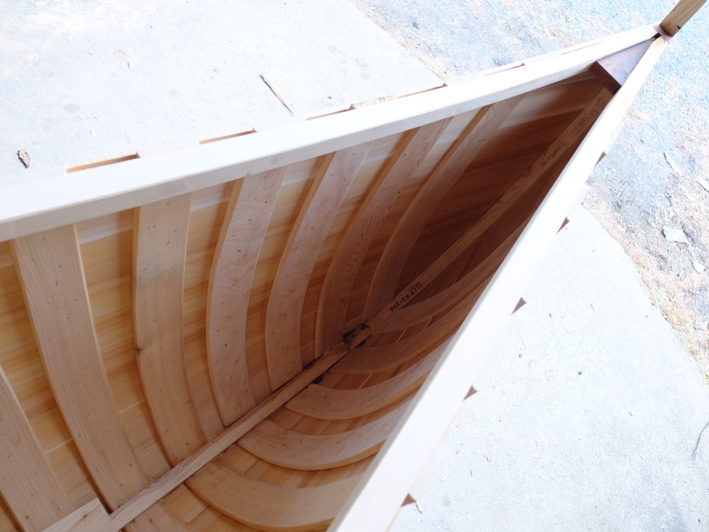
This is how it looks installed – it sits on top of and inside the gunwale.  I’m going to screw it down into the gunwales and glue it with epoxy.  DSCF0868It goes without saying that a lot of decisions get made in a project like this.  My last building remark should have raised an eyebrow or two from purists.  I am well aware that being able to disassemble a boat for repairs over the long haul is a consideration some give high priority to, but my tendency is to focus of keeping the boat together and worry about getting it apart later, if ever.  This whole boat (at least, the outside of the hull) is getting encased in epoxy and fiberglass.  I think gluing on the deck keeps water out of the deck/gunwale joint and stiffens the whole bow section considerably.  I plan to epoxy as well as bolt the thwarts to the gunwales for a similar reason.

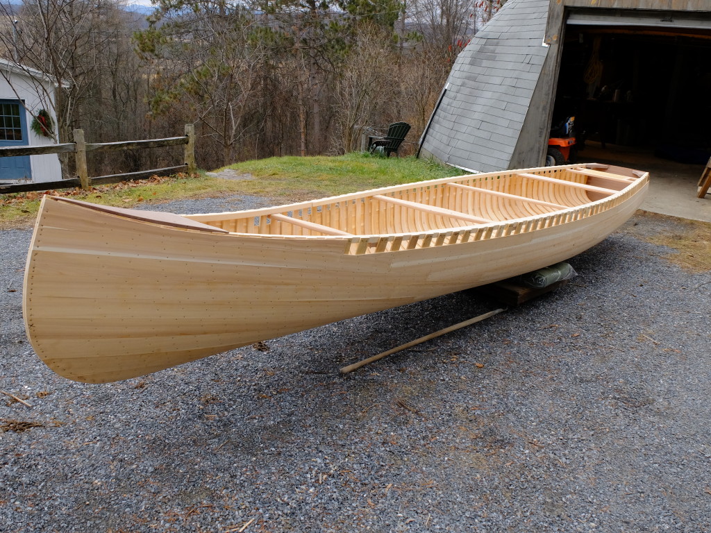
I have spent a lot of time lately gleaning information about the Grand Laker canoes from any source I can find.  One thing is clear, that for the builders in Maine around Grand Lake Stream, they were not averse to adopting new materials that were an improvement over what was previously used – like the use of fiberglass instead of canvas to cover the hull once the lead went out of paints.   This decision, almost universally adopted by the Grand Lake builders, is still controversial to ‘purists’.  Do the builders in Maine now glue in their decks and thwarts?  I don’t know, and I don’t want to ask.  I have encountered with them an interesting form of reticence that makes it impolite to ask too many questions.  I have a couple contacts up there who have been helpful with pictures and tips, but there is a history of independent living and self-sufficiency among the past and present builders that makes sharing design and construction details too personal.  I found an article in the May 1994 issue of Field and Stream by Jerome Robinson about the Grand Lakers.  He found it almost impossible to even buy one – how much to they cost?  Can’t say.  Can he order one?  No – don’t want to be bound to a time line.  Could he make a down payment to hold one?  Nope – don’t want to hold somebody else’s money.  But lo and behold – the next spring one had been built for him and was ready and waiting.  Robinson goes on to say of the builders, being self-sufficient and resourceful, ‘they’d sooner die than ever talk to each other about how they build canoes’, that they’d be out on the water all day and study each other’s canoes but never discuss materials or techniques or how much to charge, each man would figure it out for himself.  Jerry Stelmok (and Rollin Thurlow) in The Wood and Canvas Canoe say the Grand Lake builders worked independently and never developed a single strong canoe company, each man using canoe building to supplement his income as a guide.

The foregoing tends to explain why it has been difficult for me to get construction details.   I recognize that I am going against this tradition by writing up my building experience.  But I see no reason (there may be a good reason I will see later) not to share what I have tried, and what I learn.  There are very few builders of these boats now, and whatever my production is, it won’t be a threat to the real builders in Maine.  I hope I don’t lose their respect by passing on what I learn from them and what I try.

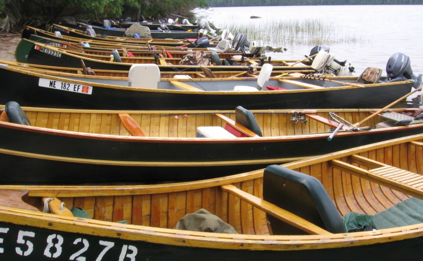
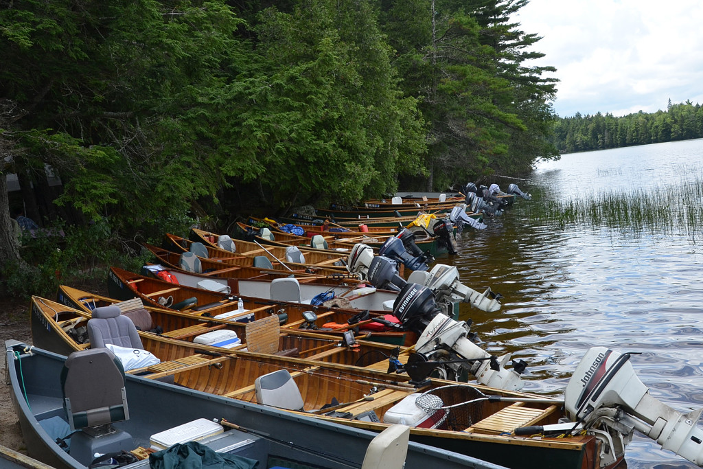
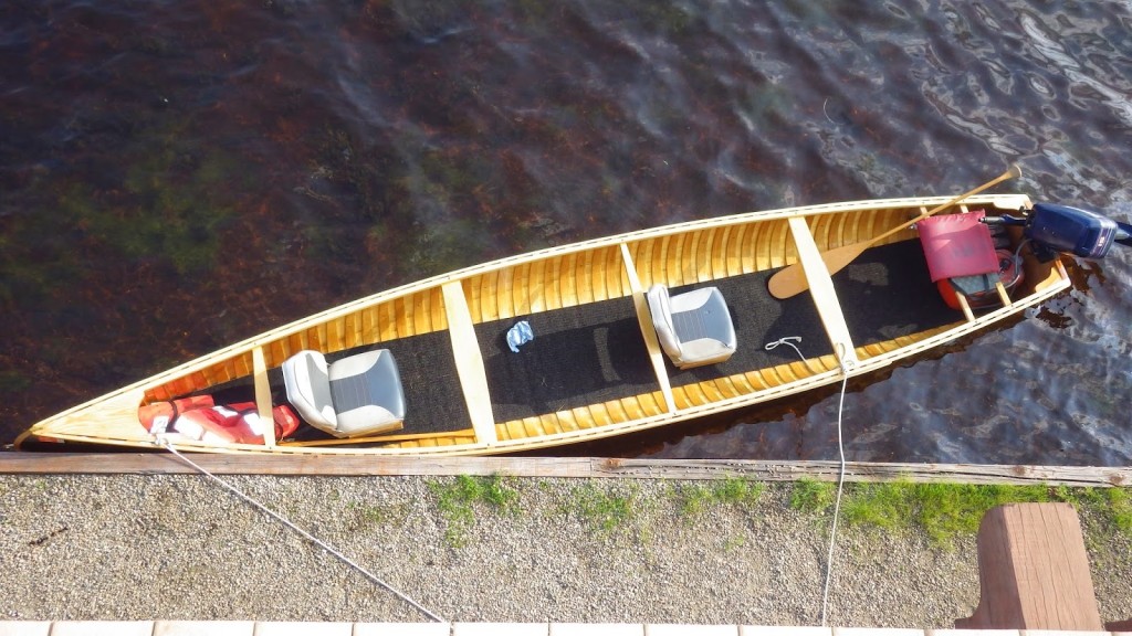
Which brings us to thwarts.  Where do they go, really?  And, why do I want to glue them in?  This picture, from Mike Remillard, gives a good idea of the options for seating and thwarts – SS Canoes 005Almost all the boats are set up for 2 fisherpeople, and the guide.  The guide’s seat is always a canoe-style seat set just below the gunwales, and the seats for the sports are generally automotive/powerboat-style, facing backwards for trolling.  Two of the thwarts, those facing the sports’ seats, are wide enough to sit on for casting.  On some boats those wide thwarts have short lips on the edges so the thwarts also act as a place to keep things like a beverage container on.  A smaller percentage of the boats are set up with the sports’ seats facing forwards.  I spent some time trying to scale the thwart locations off images like the one above until I realized I could use a rib count to find the distances between thwarts – ribs are generally 4″ on center.  Fifty-four ribs between deck and transom = eighteen feet, plus two feet of deck = twenty feet.  This picture of a Dale Tobey boat at Paul Smith’s College at a WCHA gathering was very helpful – I get about 7 ribs from the transom to the front of the rear seat, 9 ribs rear-seat-to-rear thwart, 11 ribs between each of the next three thwarts, 6 ribs to the deck, and roughly 6 ribs to the stem.  This translates to 28″ transom to front of rear seat, 36″ to rear thwart, 44″ between each of the main thwarts, 24″ to end of deck, and 22″ of deck.  This adds up to : 242″, or 2″ over 20′ which is the assumed length of the boat.  This is close enough to work with.  Tobey GL at Paul Smiths WCHA 2014I followed that basic layout, using black cherry for the thwarts and seat frame, and machine cane for the stern seat.  The after-most thwart is just a 6″ wide plank suitable as the ‘beverage platform’.  I dragged the boat out into the driveway to have its picture taken.  Next – finish the planking and clench all the tacks.DSCF0880

Planking and coming off the form

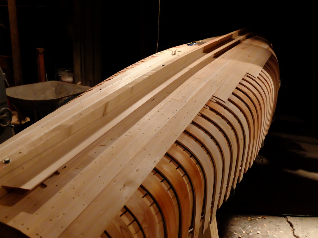
My planking measured 3/16″ x 2 7/8″, the vast majority of it clear, close grained, quartersawn.  Very good cedar.  Tacks were 13/16″ from DB Gurney.  Anywhere the planking was bent much, either strong twist or cupped around the bilge, I soaked it in rags I kept in the boiling kettle.  A couple minutes softens everything up so it will bend without fracturing.  I also soaked any place it looked like a tack might split a plank – like at the transom ends.    The ends of the half ribs are held down with bent nails from inside the form that get pushed out of the way as planking proceeds.  DSCF0822Half done with the bottom

DSCF0828

The gored area

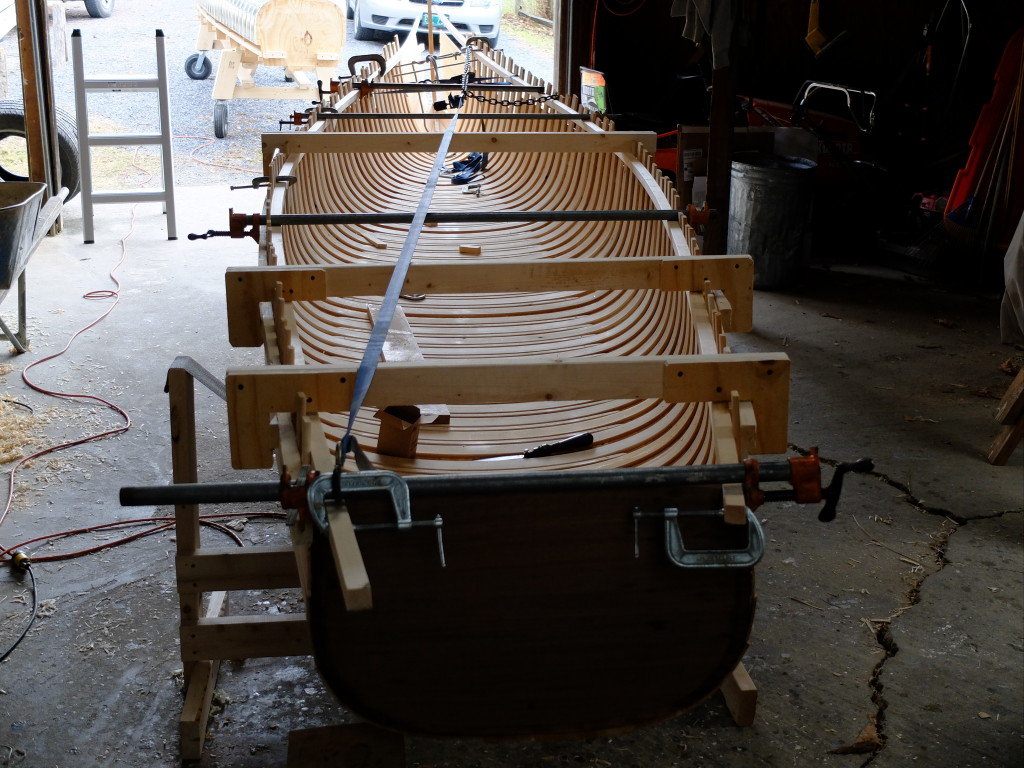
DSCF0832I took the planking within 2 planks of the gunwale and took the boat off the form.  The residual tension in the ribs/gunwales fractured one of the gunwales when everything expanded – I removed the broken gunwale –DSCF0833and put a new one in.  It took most of a day.  Below – pulling the hull with the new gunwale into shape –DSCF0835And all tied together at the stem and transom.DSCF0838

Bending Ribs

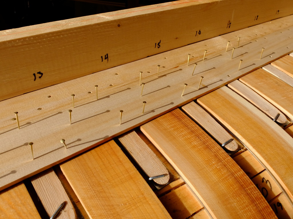
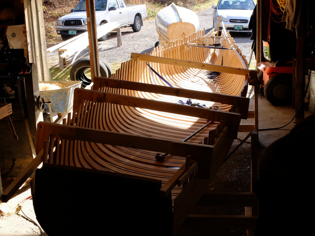
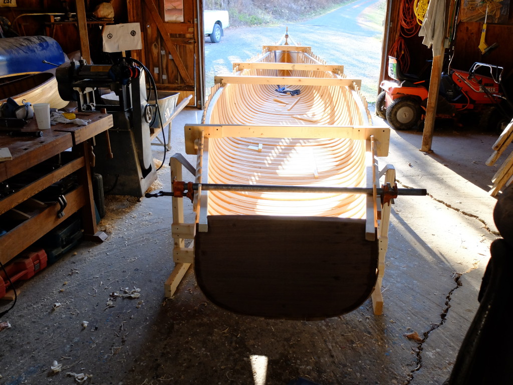
There are 54 main ribs, 2 1/2″ x 3/8″.  There are a few less half-ribs that will go on after I fair the main ones.  There was a preponderance of close-grained, quarter-sawn material in my rib stock, which is not best suited for bending – but with cedar you use what you have for material.  We broke 6 ribs out of the original 54, and bent the replacements the next day.  This bending experience was difficult than others I have had; next time I am going to soak the ribs overnight, use a bigger burner and make a bigger steam box.  My present burner is a 15,000 BTU gas hotplate and I am upgrading to a 54,000 BTU blaster from King Kooker.  My box is now 6×6″ inside, and I will make one at least 8×8″, as well as monitor the temperature inside the box.  You need 200 degrees F.  The ribs have a 3/4″ taper over the last 12″ of one side to visually offset the cant of the backup bands.  The ‘bevel goes to the center’ of the form.  The ribs that bent without breaking required slow, steady pressure that took somewhere around 30-60 seconds to bend each side, once started.  You can feel the wood give as it takes the turn of the bilge, but past the turn there is little bending going on and  this is where some of the retained tension is.DSCF0809I had a helper, John Leonard, working opposite me.  DSCF0810By the end of the first day, the form looked like this – the spaces are the broken rib spots.  We developed a fear of working up at the stem.DSCF0811

All the ribs on.

DSCF0816

Grand Laker-type Canoe – assembling the form, stem, inner gunwales and transom

First, a disclaimer – my object in building this canoe is to honor the skill and aesthetic standards of the builders who originated these boats and the methods they perfected of building them.  Although I have developed my ‘own’ set of lines, they are based on boats built by others – Dale Tobey in particular.  My design, which I hope will be successful, will never be a ‘Grand Laker’ – but it will be a Grand Laker-type which closely models boats I measured in Maine that originated in Grand Lake.   My thanks and respect go to the builders who have helped me with information and construction tips, including Jerry Stelmok and Rolin Thurlow, and Dale Tobey by way of pictures he has posted of his boats, and his comments on the WCHA site.

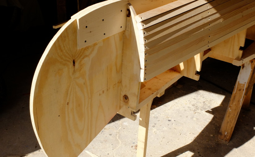
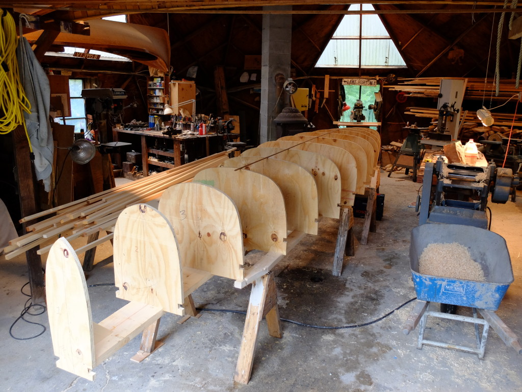
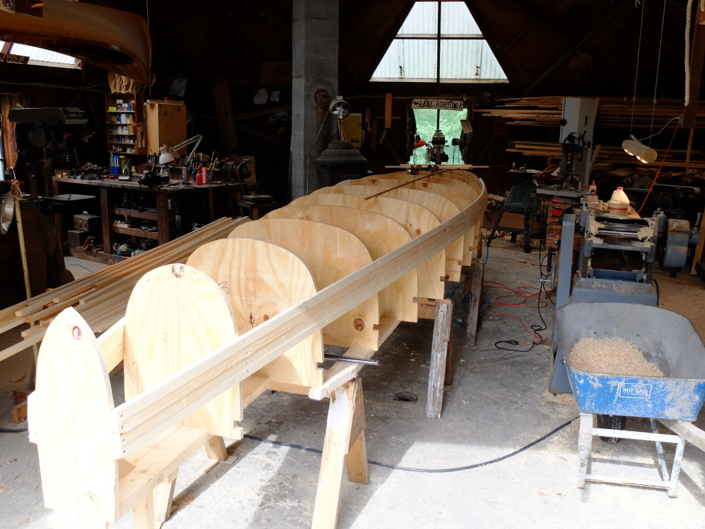
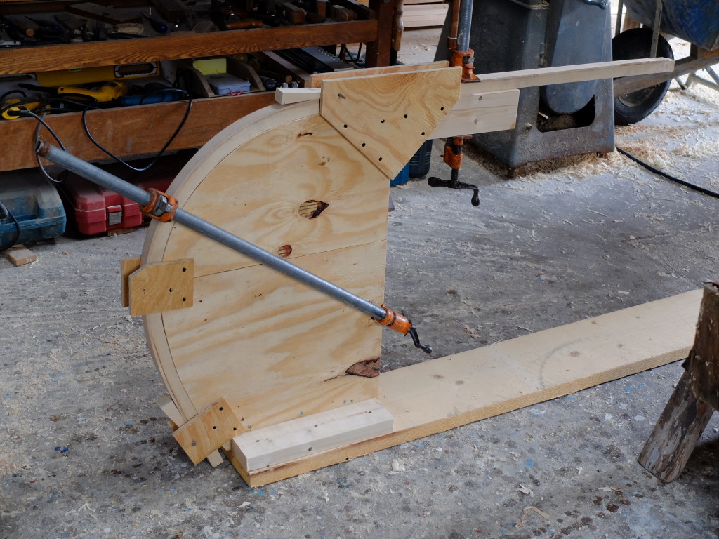
The form stations assembled on a 2×8 plank backbone with 2×4 outer members taking a lot of care to assure everything was level and plumb.  The stations are glued and screwed into dadoes cut in the backbone.

DSCF0722

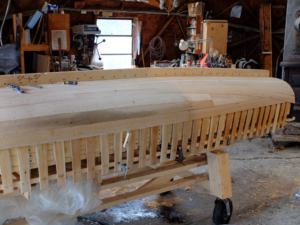
The first of the 7/8″ x 1 1/8″ pine sheathing strips went on about 8″ below and parallel to the gunwale.  Shorter strips that were manageable to saw were joined with glued and screwed butt-blocks to make up the 19′ strips needed.  In the picture below, the stem form has not yet been added.

DSCF0727

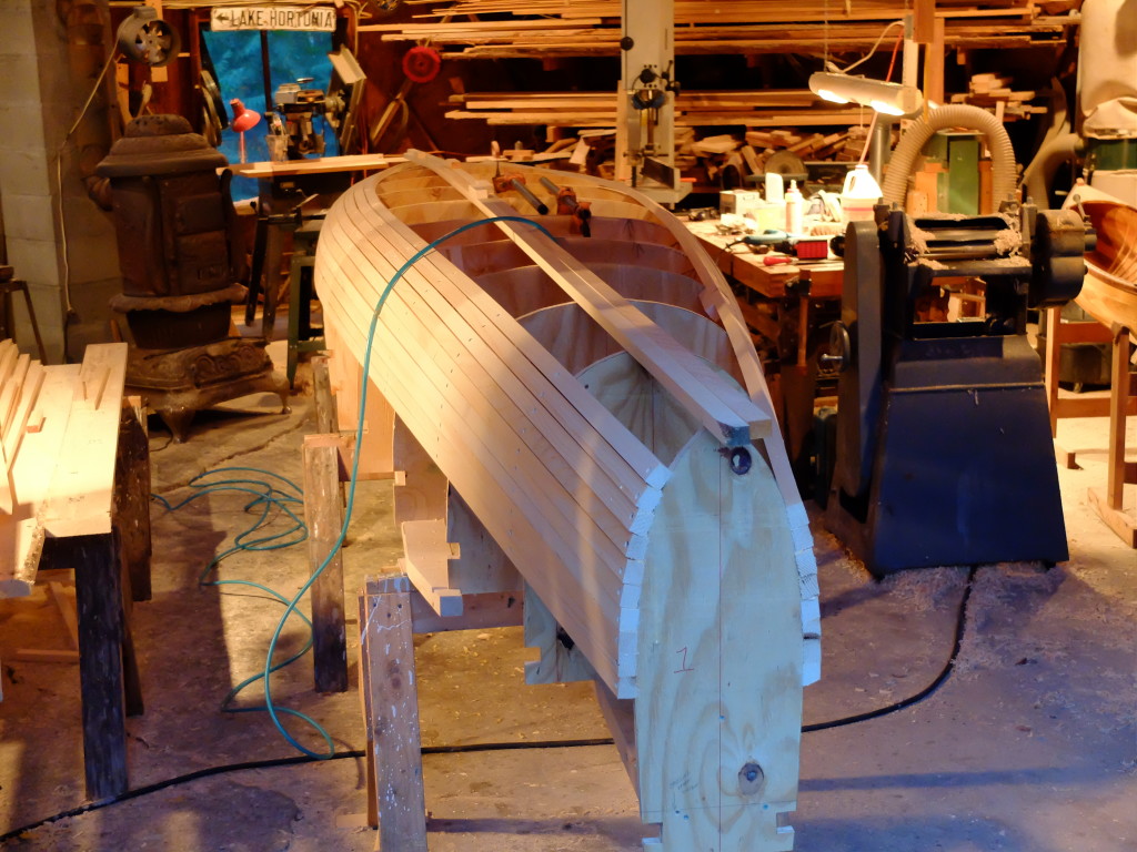
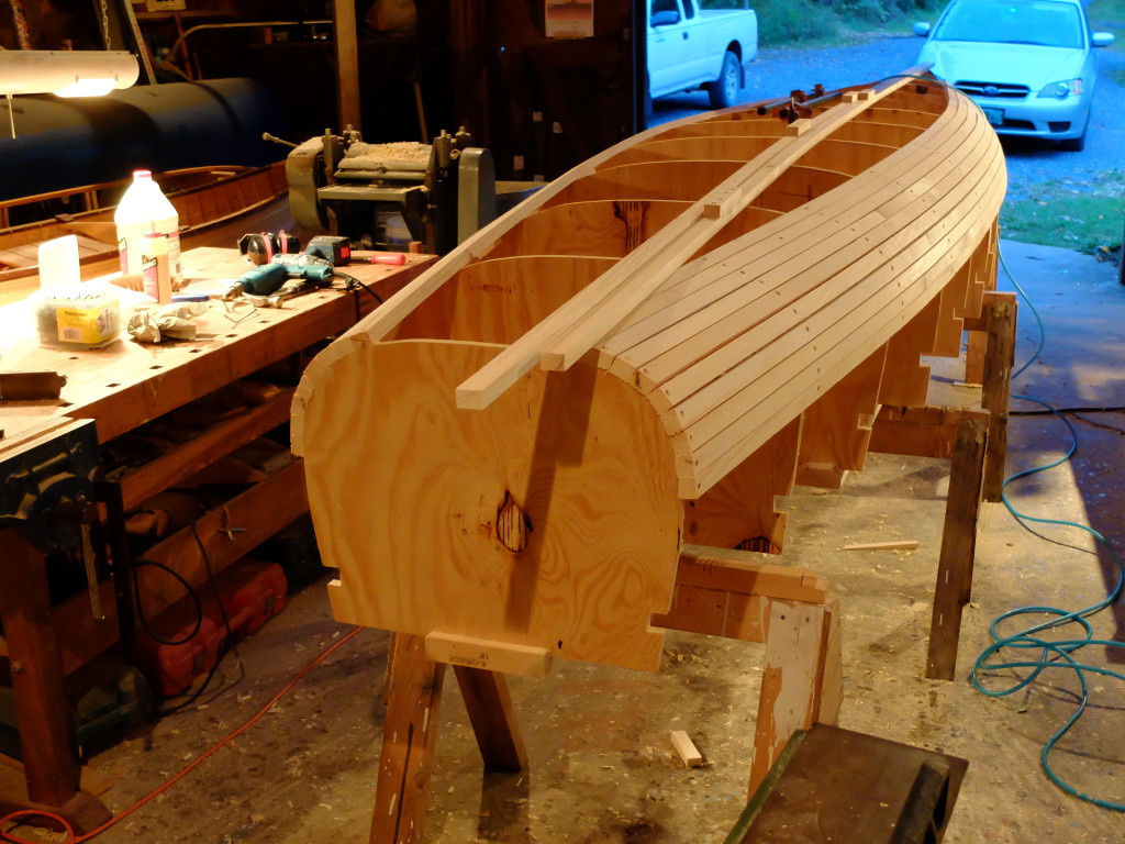
Working towards the bottom – each strip glued and screwed to the frame and glued and nailed to its neighbor with 2″ air-gun finish nails.

DSCF0732

Stern view

DSCF0734

It was very exciting to see the shape develop smoothly with a few exceptions that were addressed by shimming three stations – watching for unfairness as the strips went on clearly showed where I needed to correct the offsets, which in retrospect were evident in the lines of my body plan.  The table of offsets previously posted has been corrected accordingly.

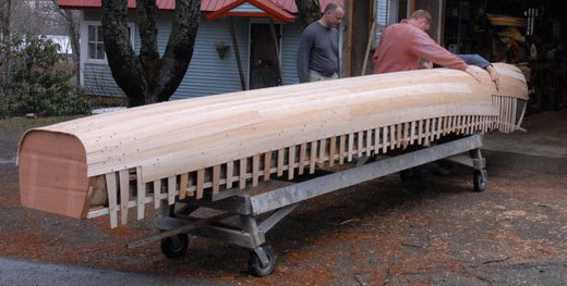
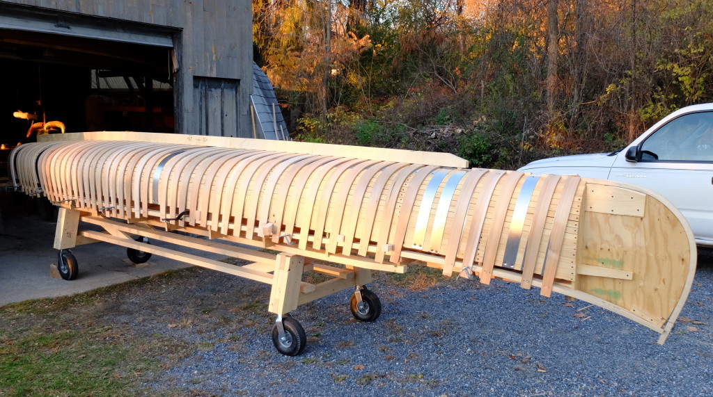
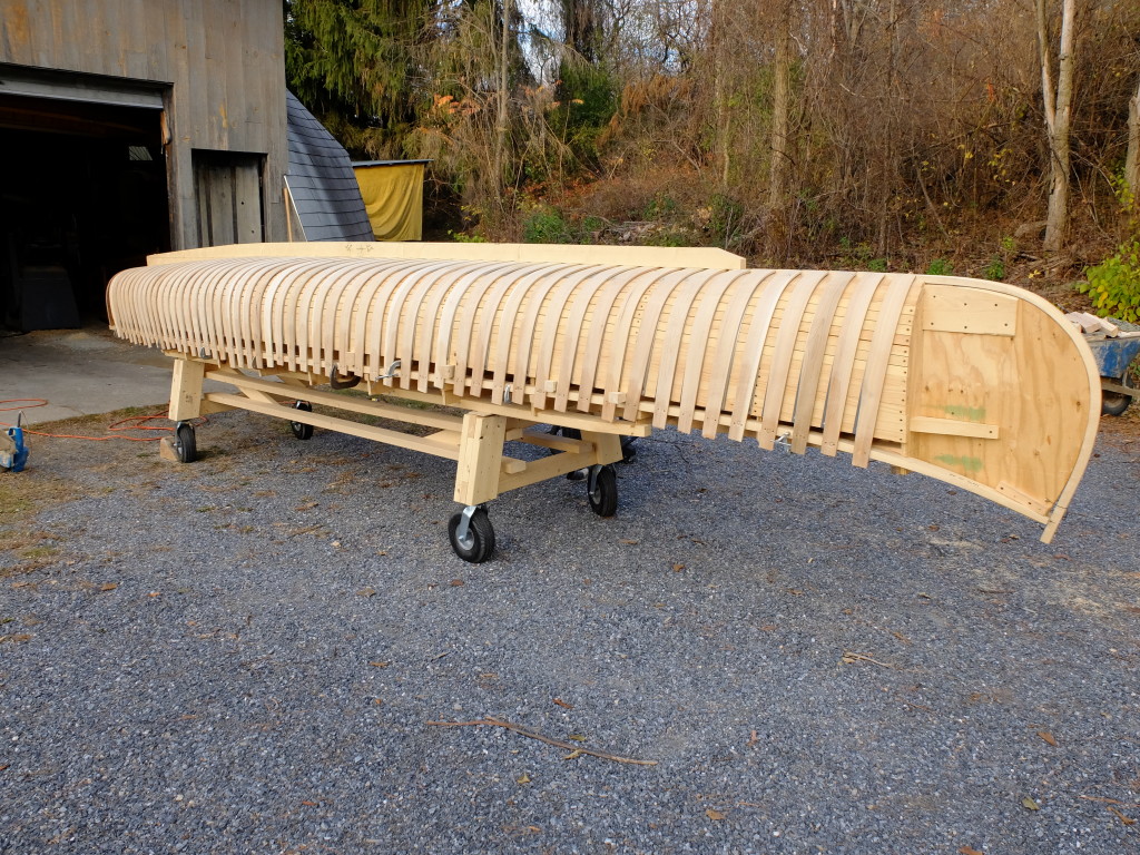
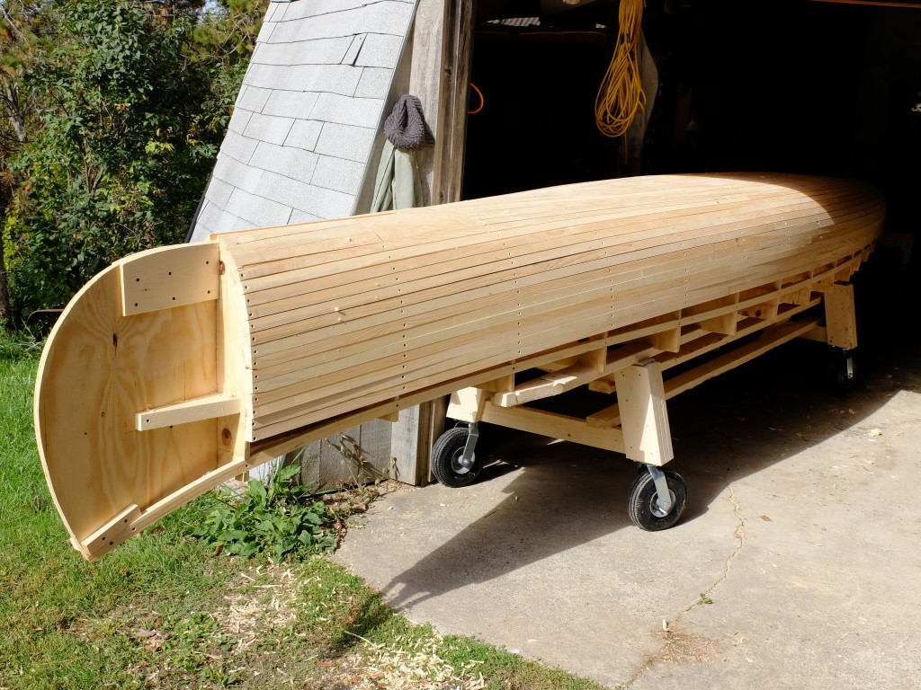
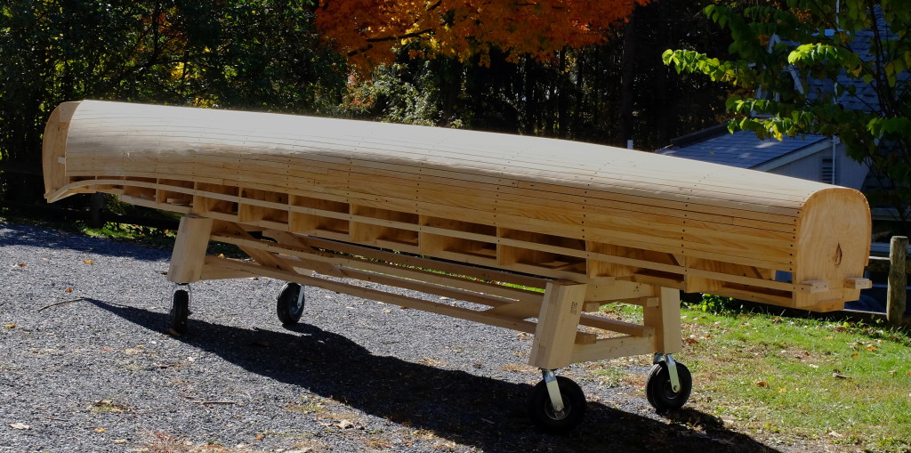
Storing and moving the form around – how to?  I found this picture posted by Weatherby’s of a Pop Moore boat on its form – the form has a wheeled undercarriage.  Great idea.  GL Pop Moore 2I did the same.  Below, the form before fairing and adding the metal bands.DSCF0753

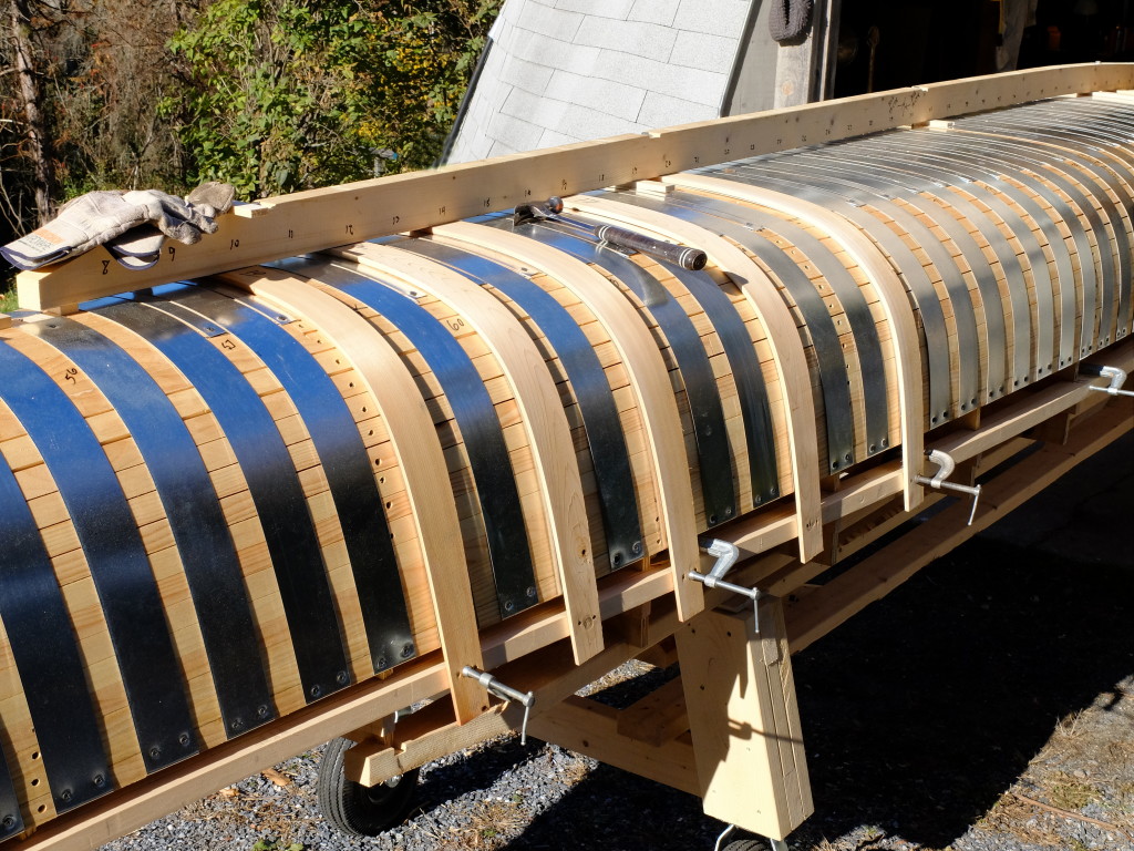
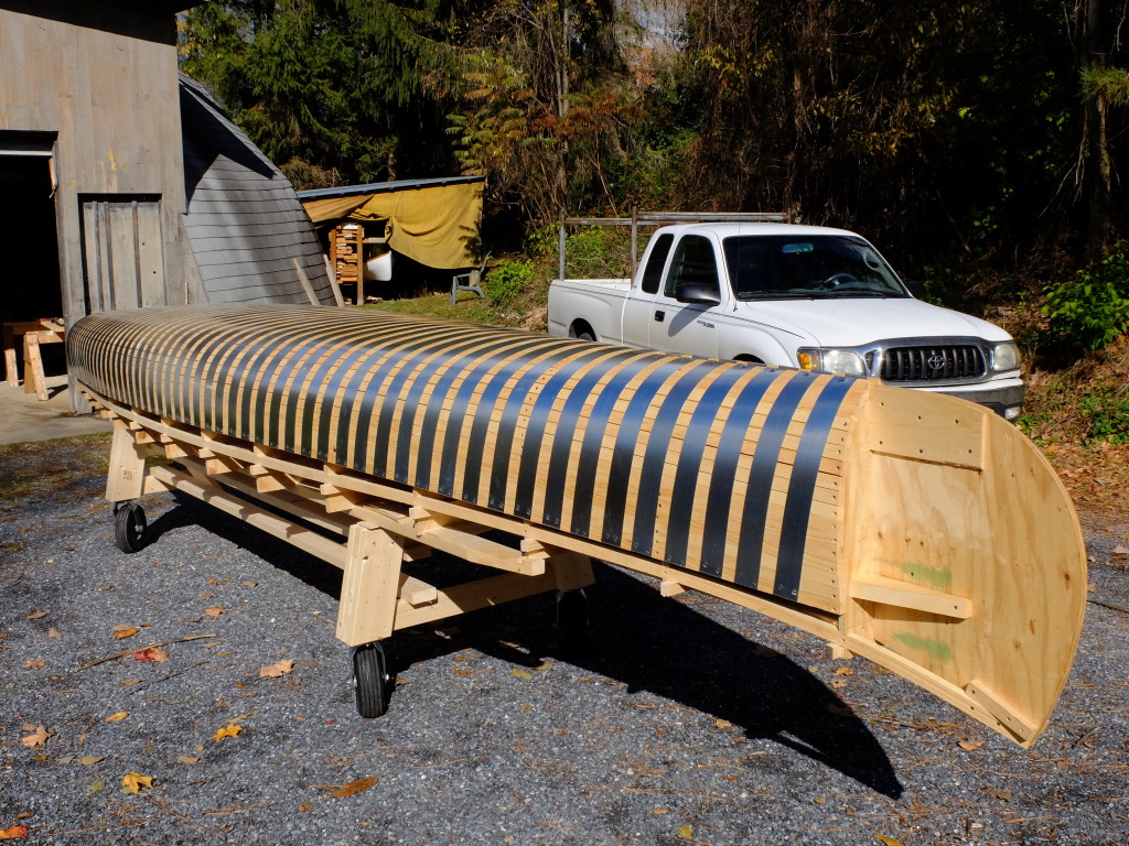
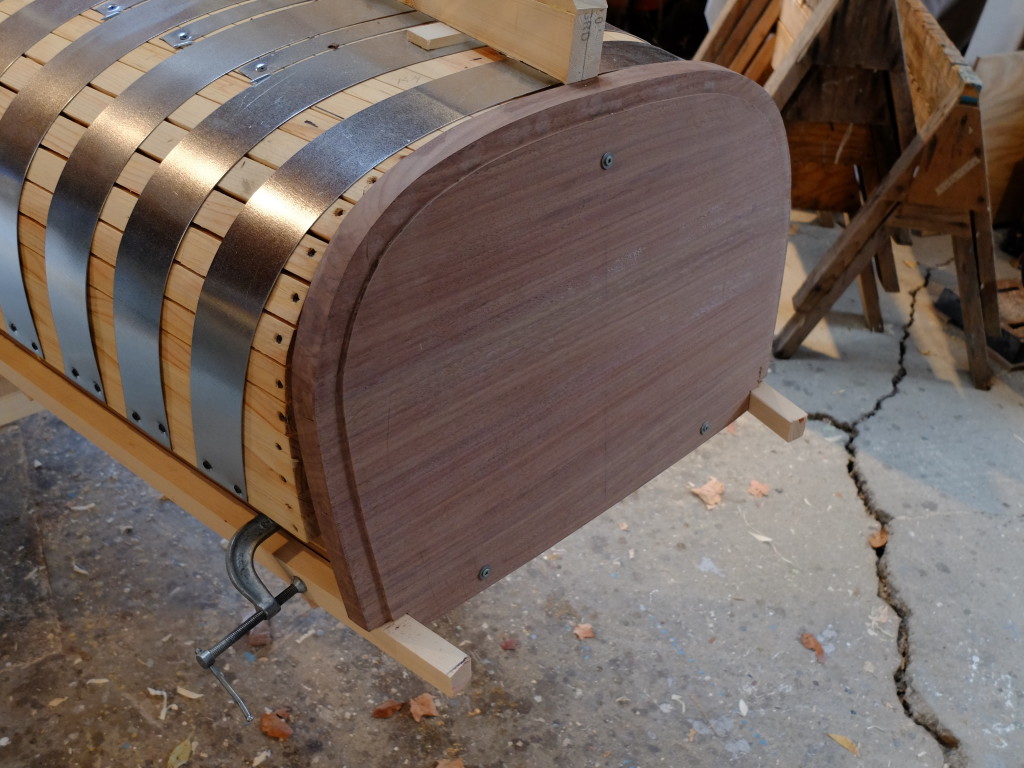
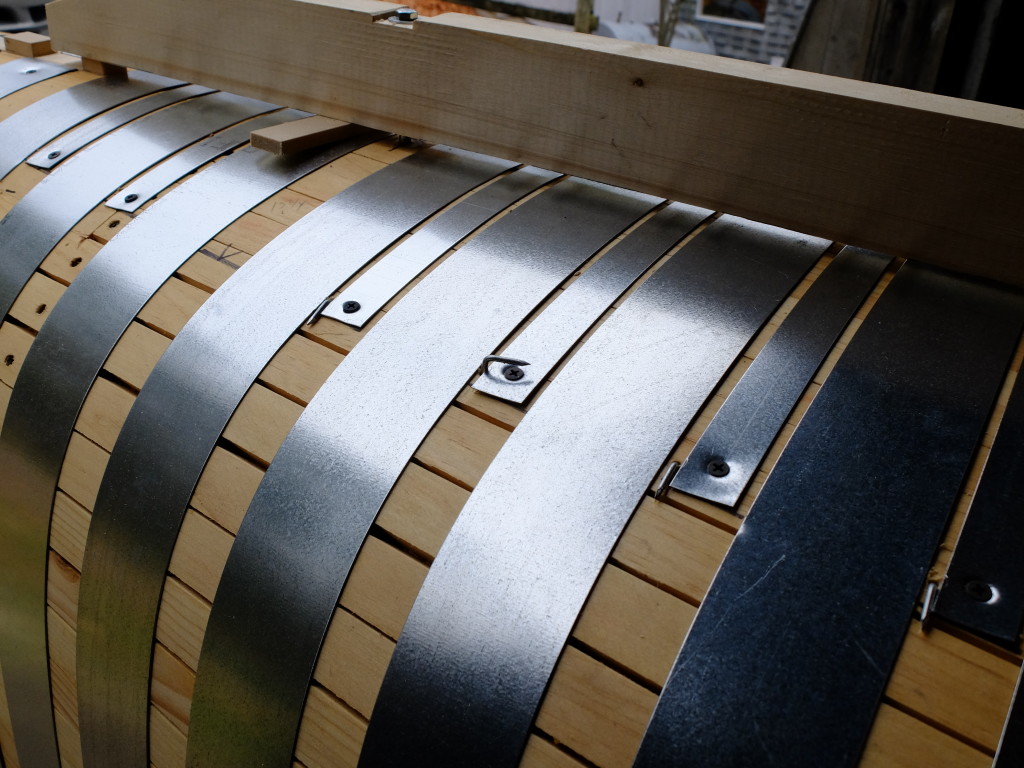
DSCF0769After (2 days of) fairing the form.  Coated with boiled linseed oil thinned with mineral spirits.  Below – with backup bands for ribs, 2 1/2″ 20 gauge galv. steel, 4″ on center.  This form will have half-ribs through the bottom, with backup bands 1″ wide, yet to be added.DSCF0784

The stem – 1″ square ash, fresh cut from a green log – on the bending form

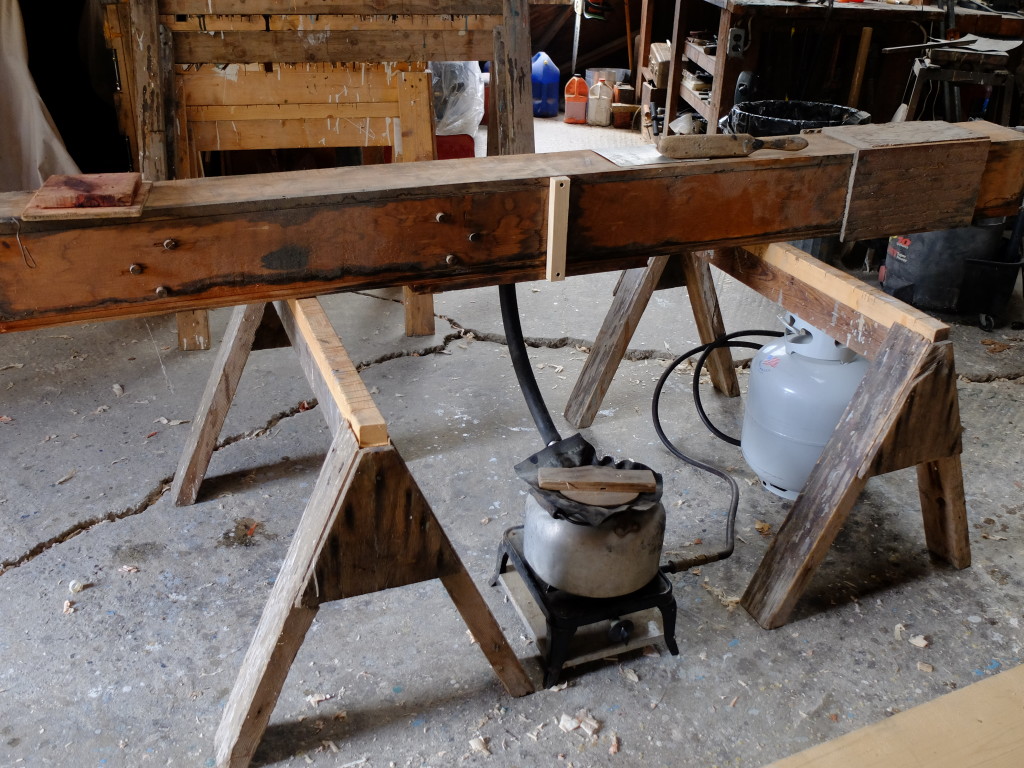
DSCF0774The steam rig – a propane hotplate, an old kettle, a piece of radiator hose and a pine box – I let the stem steam for an hour and it bent with careful pressure.

DSCF0775

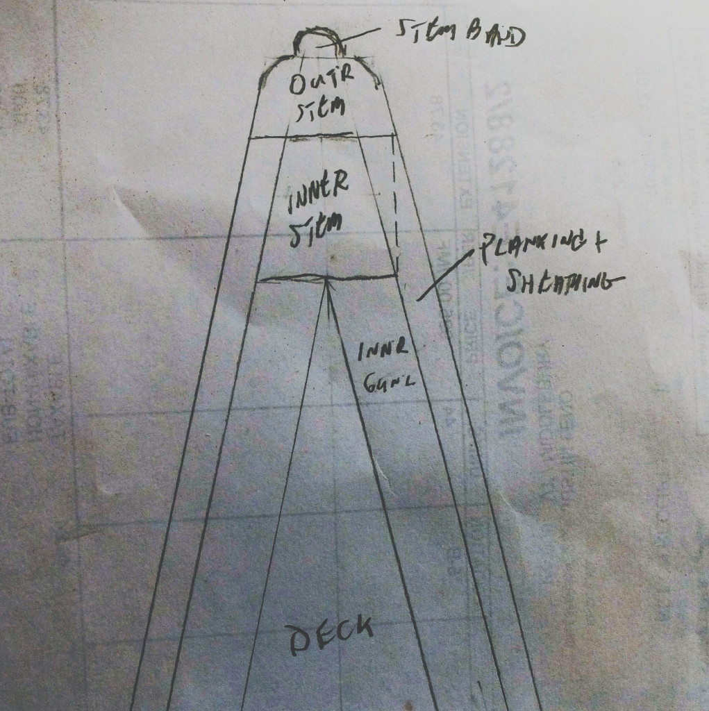
Inner gunwales are spruce, 1″ x 1 1/8″ – very hard to find clear pieces 21 feet long.  These were cut from a 2×12 – 22′ found at the local lumber yard.  I got enough material for both inner and outer gunwales.  The upsweep at the stem is strong enough to require steaming and pre-bending the last 3′ of the gunwales in a jig.  They taper to 1/2″ wide x 3/4″ tall at the stem.  The stem layout – The inner gunwales will butt up behind the inner stem and attach to the stem with a small knee.DSCF0799The inner gunwale gets clamped to the gunwale backer on the form so it sits vertical, and has to be tapered on its outside face for the flare in the forward sections of this boat, as well as the tumblehome in the after sections.  This, so the ribs will have good contact where they are nailed to the gunwale.  The transom on this boat is black walnut, with a rabbet cut in its outside face for the fold of the fiberglass sheathing to sit in, and is notched for the gunwales.  The formDSCF0797now has the backer bands for the half ribs which will be held in place initially by #6 box nails bent up through the form.  The half ribs will help offset the tendency of the main ribs to spring back into a rounder shape than the hull form – I want a semi-flat bottom section.  The strongback is bolted through the form to T-nuts inside.  When bending the ribs, it will hold the middle of the rib down and prevent things from shifting around until the planking goes on.  The form is now ready for the ribs to be bent and nailed to the inner gunwale.DSCF0795