
A place I go for a week each year on the Maine coast has a half-dozen utility skiffs that are understated gems.
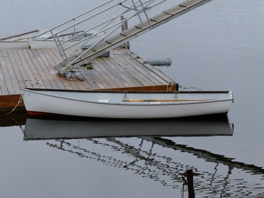
They row well, have good carrying capacity, can take a low horsepower outboard, and sail fine with a simple sprit-rig if equipped with a centerboard. They can be beached and dragged off the rocks with the coming and going of the tide. It would be nice to have one for kicking around, and I decided to at least try to take the lines of one of them to document the design, and be ready to build one if I ever got fired up enough about it. I’m sure there are plans for similar boats available, but the process of drawing up your own lines is interesting. For the time being, I have left the decision of construction method undecided.
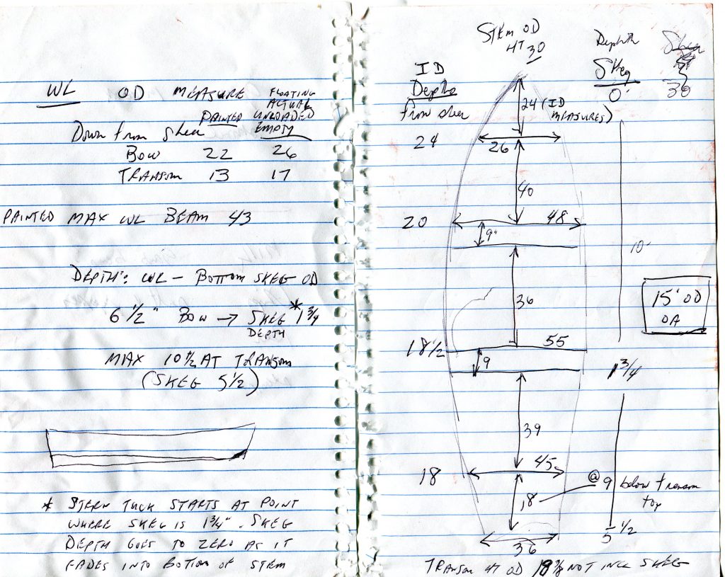
I made cardboard templates of the inside of the hull at two places, about 2′ ahead and abaft midships, as well as a tracing of the transom (expanded view). I got overall length, and beam at gunwale at four places, plus the transom. At those same beam locations, I measured inside depth from keelson to top of sheer.
From a boat upside down in a field I got a look at the run of the keel, the amount of tuck in the stern, and some waterline depth measurements.
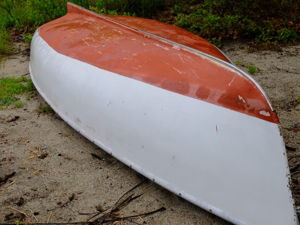
Most of these boats show some hogging in the keel, I believe caused by shrinkage of the fiberglass as it cured; the keel fiberglass areas probably got hotter due to more allowed to set up at once. The hogging is not a design feature, and I would not incorporate it into my design. This boat, above, had a centerboard.
Given the measurements I had taken, I was ready to start to draw the design and loft the lines to check for fairness.
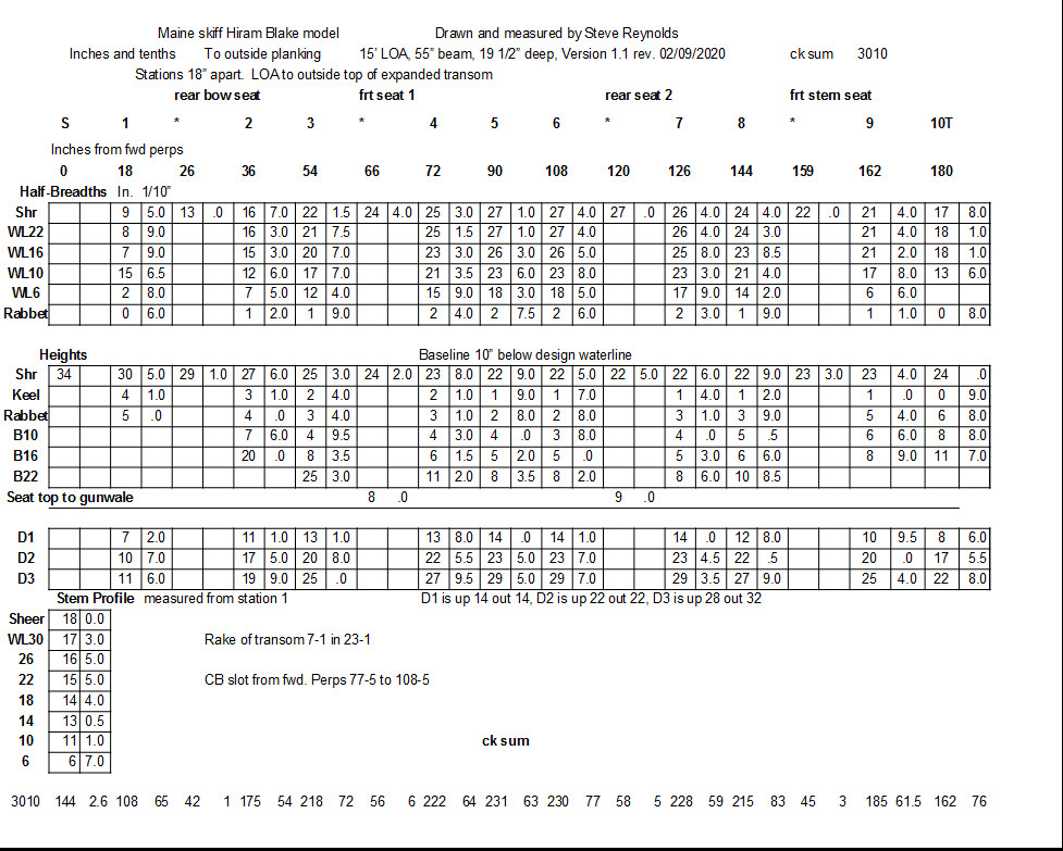
This is where the problem of lofting scale had to be addressed. The past two boats I have lofted were 20-footers, and I drew them up at 1/2 scale so I didn’t have to provide a 20+’ space, which was going to be difficult. On those boats, I drew a body plan full size – this took only a piece of plywood roughly 36″ x 44″ – measured the offsets on that plan and transferred to a spreadsheet, then divided all the measurements in half. The profile and half-breadth plans could be done on 10′ of plywood instead of 20′. This worked, but was cumbersome. On this new boat, I came up with the expedient of drawing in centimeters. Given two rules, a metric and an inch ruler, I could go back and forth with no conversion. The drawing comes out to be 40% the size of the full boat, or, about 6 feet for a 15′ boat, which I found manageable, and accurate enough for what I intended. I am presently done with the first round of fairing the lines. Below is the table of offsets.
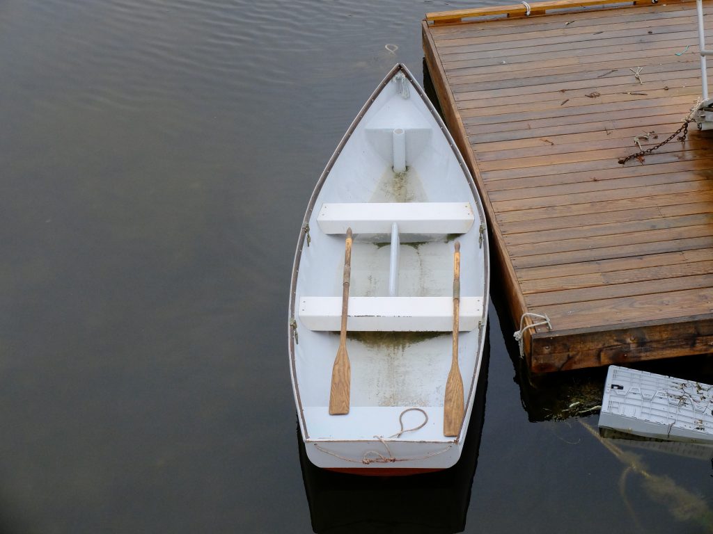
Here is an overhead view of one of the boats.
I think the next step is to make a half-model at a 1″-1′ scale.