Fiberglass vs Canvas Canoe Covering

I now have four years experience with this boat. We have just come back from a camping trip where we had a lot of stony landings. In total we have probably dragged the boat ashore and launched over a 100 times since it was new, and I thought I needed to check the condition of the bottom to see how much damage had been done. This boat is the one described in the earlier blog entries, the exterior finished with a double layer of fiberglass cloth set in epoxy. I have built several cedar/canvas canoes with the traditional filled canvas covering, and the Grand Laker type canoes are in the same line; however, all the current builders of lakers I have talked to now use fiberglass because of its toughness, and I followed their example. I am well aware of the deviation from the traditional approach. I still run into other boaters who see fiberglass on a cedar canoe and say ‘big mistake’. I therefore want to give a brief report on the condition of my boat after 4 years of use and reiterate the reasons why I think fiberglass is a good choice.
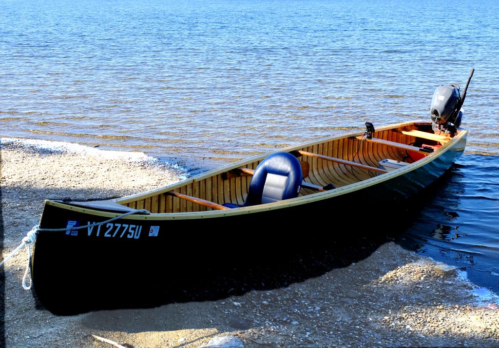
This is the beach at our campsite. It is made up of coarsely rounded gravel averaging about 1/4″ in diameter, and we dragged the boat on and off the beach at least 3 times a day. This was the smoothest landing we had during this trip; others consisted of sharply angular fill, and a couple were unusable altogether. We didn’t hit any rocks in the water, but that could have happened. We are not young people and when it comes to choosing between letting the boat take the knocks, and us struggling with it, the boat has to look after itself. Fully loaded, we are carrying about 750 pounds of boat, motor, gear and people, and some of the landings happen with a loaded boat. I came home working on a plan to repair what I thought would be significant gouges in the fiberglass. I was pretty certain that, had the boat been covered with canvas, I would be dealing with rips and tears.

My repair plan was to sand the bottom of the boat back to bare epoxy, put on a thin new epoxy coat to fill the scratches and seal any fiberglass exposed, and repaint. What I found was that the bottom is still sound. The paint is worn where the boat is grounded out, the only scratches approaching any kind of need for attention came from earlier trips where we had hit rocks on the move while loaded. But nothing needs to be repaired at this time.
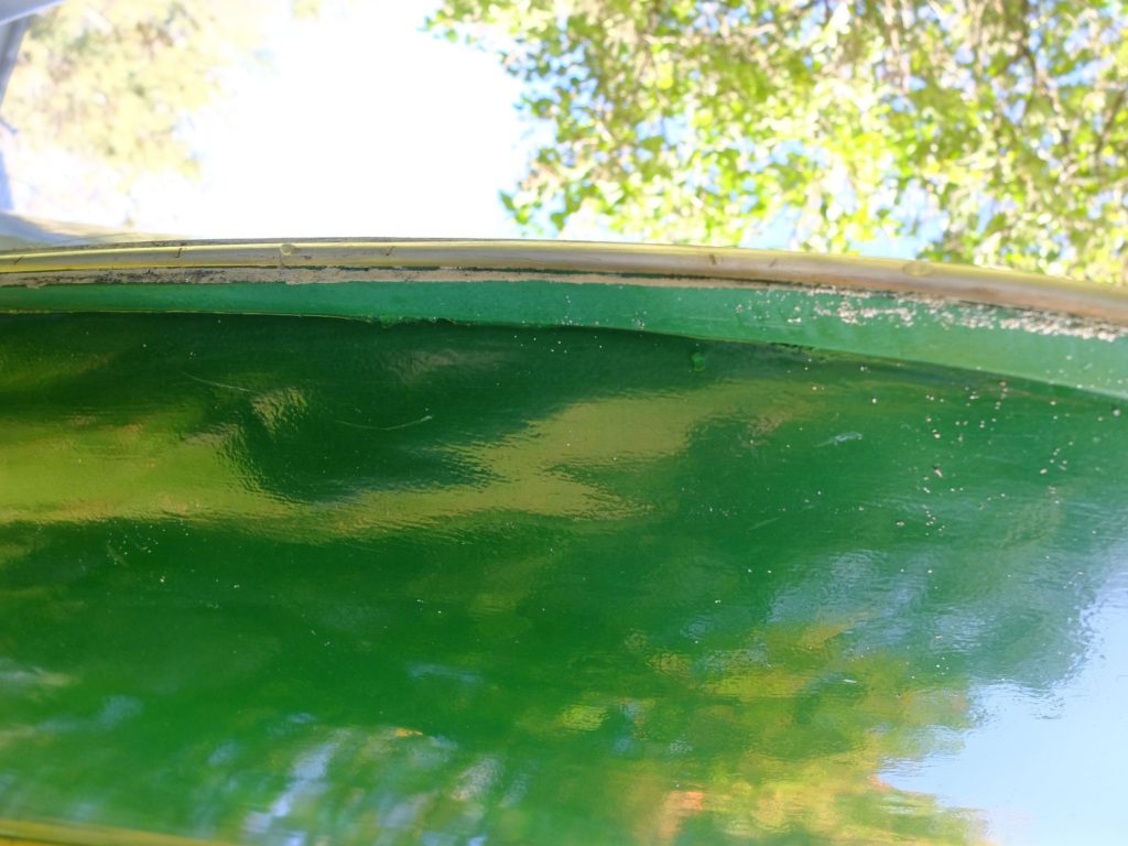
This is the bottom of the stem. The keel projects 3/4″ and is capped with a brass band for about two feet back from where it enters the water and is effectively doing its job of taking the brunt of the landings while protecting the fiberglass skin. The stem itself is made of white ash, and the keel is white oak.
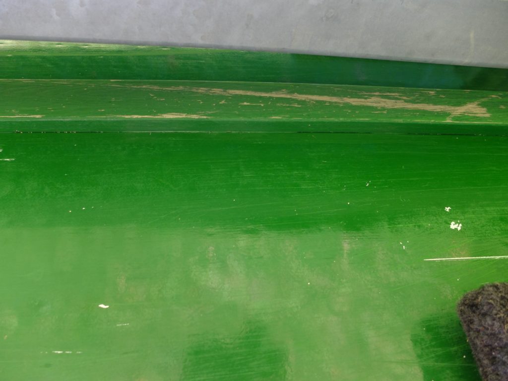
This is a little further aft; the keel widens from 3/4″ where it is scarfed to the stem, to about 3″ amidships, and then tapers back to 2″ at the transom. Again, the keel is taking the hits, some of the bottom paint is scratched but not gouged.
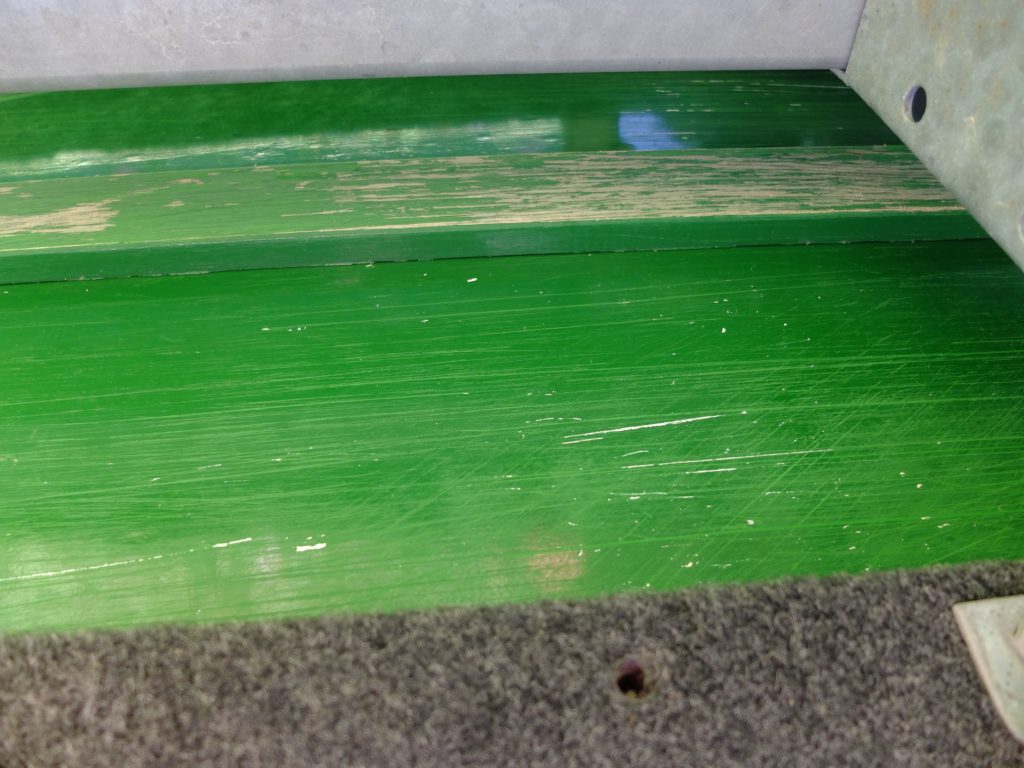
Approaching midship.
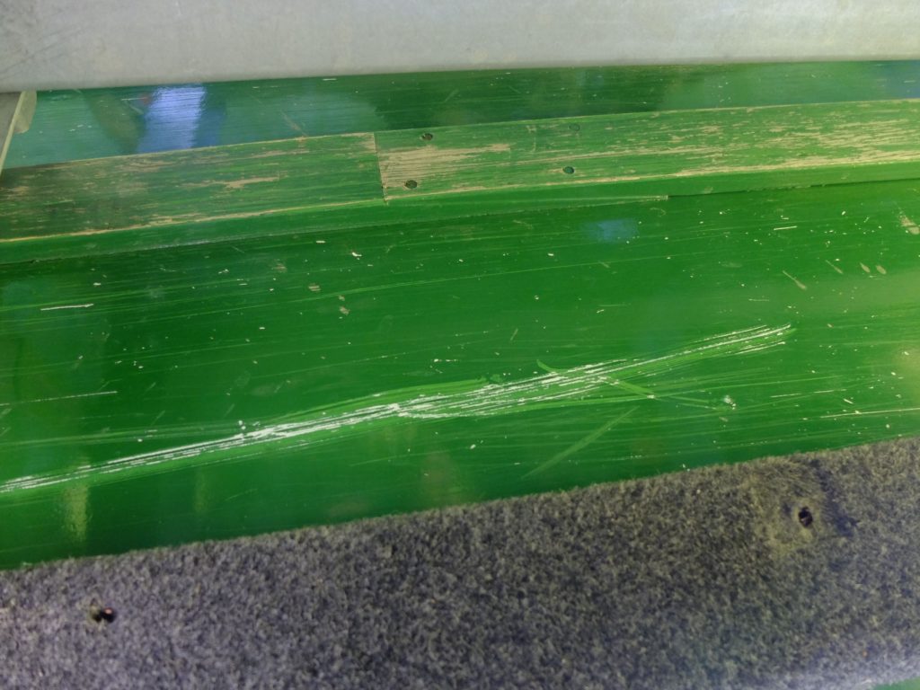
Aft of center, showing the scarf in the keel where most of the weight sits when grounded. Keel a little worn but intact, large scratch from hitting a rock while moving, but nothing to worry about.
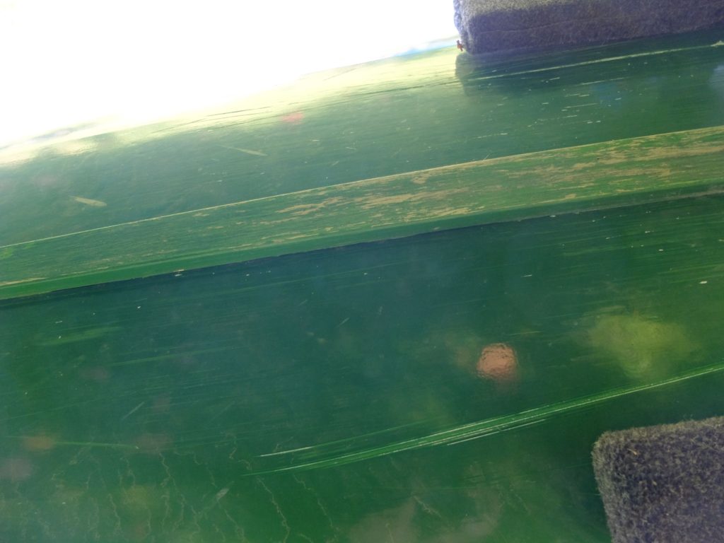
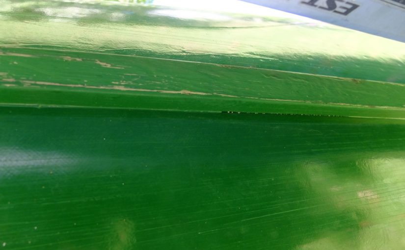
A little further aft.

So – I am happy with the performance of the fiberglass and paint. The advantages as I see them of fiberglass are :

  • It adds considerable strength and rigidity to the hull. I have no problem with oil-canning, I think partly thanks to the fiberglass/epoxy. Canvas would not add as much strength.
  • The strength helps absorb the stresses of trailering and chaffing on the trailer / tie-downs.
  • There is no space between the planking and covering in which sand can accumulate, as it can with a canvas-covered boat where sands works down from the inside if there are any gaps between planks.
  • It does not rip like canvas, nor is there any concern about rot.
  • It can cover a width of beam that is difficult to find canvas big enough for on these 20′ boats.
  • Fiberglass is no heavier and possibly lighter than filled canvas, and does not gain weight as it gets wet.

The disadvantages are all in the realm of could-be in the future :

  • The epoxy prevents the planking from expanding on the outside, while the inside theoretically can expand, creating stresses that could possibly separate the epoxy from the planking, or crack the fiberglass along the plank seams. Maybe this would be a problem if you left the boat in the water for extended periods, but that is not how I use my boat. It is in the water for a few days, then back out and stored under cover. This problem can be mitigated by using quarter-sawn planking lumber that is properly dried.
  • Replacement of rotted/broken ribs or planks becomes impossible with an epoxy skin, unlike canvas where you can take the whole think apart one tack at a time. True, but I don’t expect to break ribs or planks, and with care taken for how you store the boat, rot is unlikely. Conversely, repair of an epoxy-coated boat with structural damage can be accomplished with techniques used for repair of fiberglass boats, and presents no more difficulty, or rather is no easier, than structural repair of a strip-planked boat.

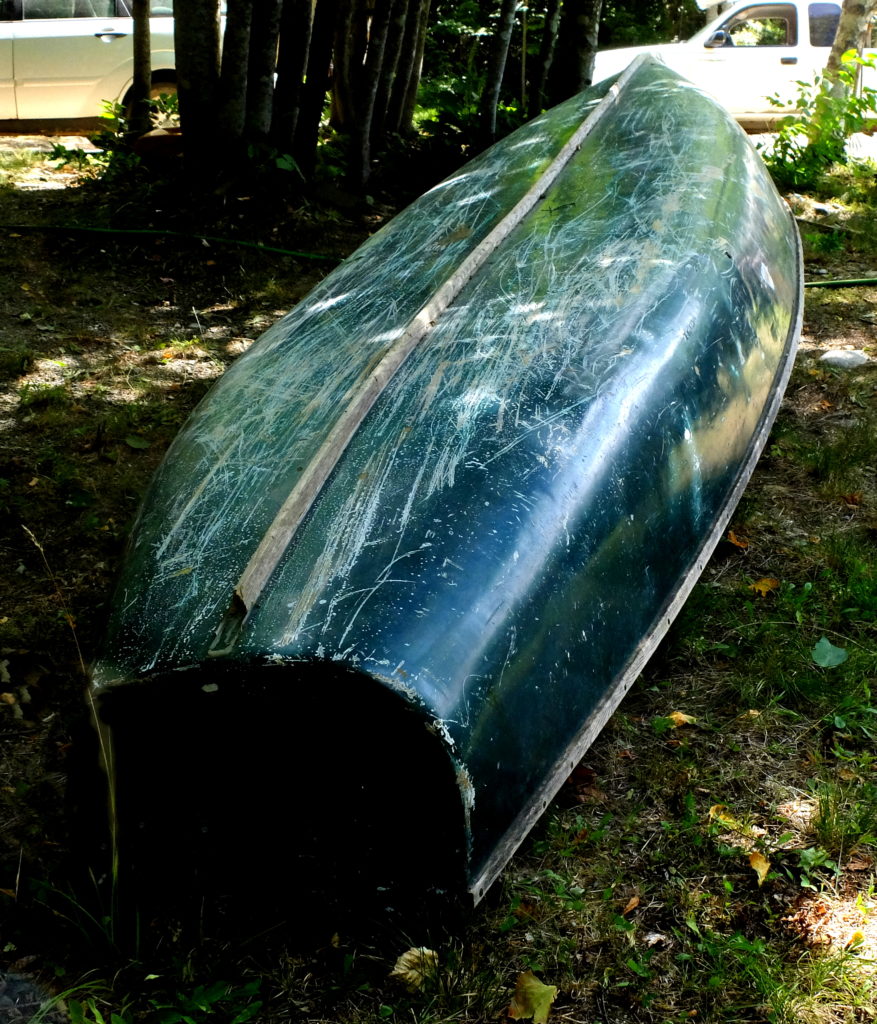
I have reached the point in my life where the question of who outlives who is no longer in doubt – unless something goes really well or really wrong, the boat will outlive me regardless of how the fiberglass wears. The boat below is fifteen years old and in need of a refinish – this particular design tends to hog pretty badly – but with a sanding, fresh filler epoxy coat, and some paint will be back in service as long as the owner wants it.
Homemade Thickness Sander / Abrasive Planer

My thickness sander is one of the tilting-table variety that lots of people make, and it continues to serve me well allowing for thicknessing delicate and/or figured wood to very tight tolerances.  It has some limitations – material width limited to about 17″, single grit that is not easily changed, maximum stock removal rate of about .010″ per pass – but I’ve found it a functional alternative to a $1,000-plus machine.  It produces accurate results far beyond what might be expected from its simple design and wooden construction.  I include pictures below of some details.

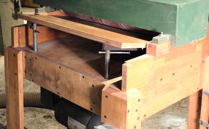
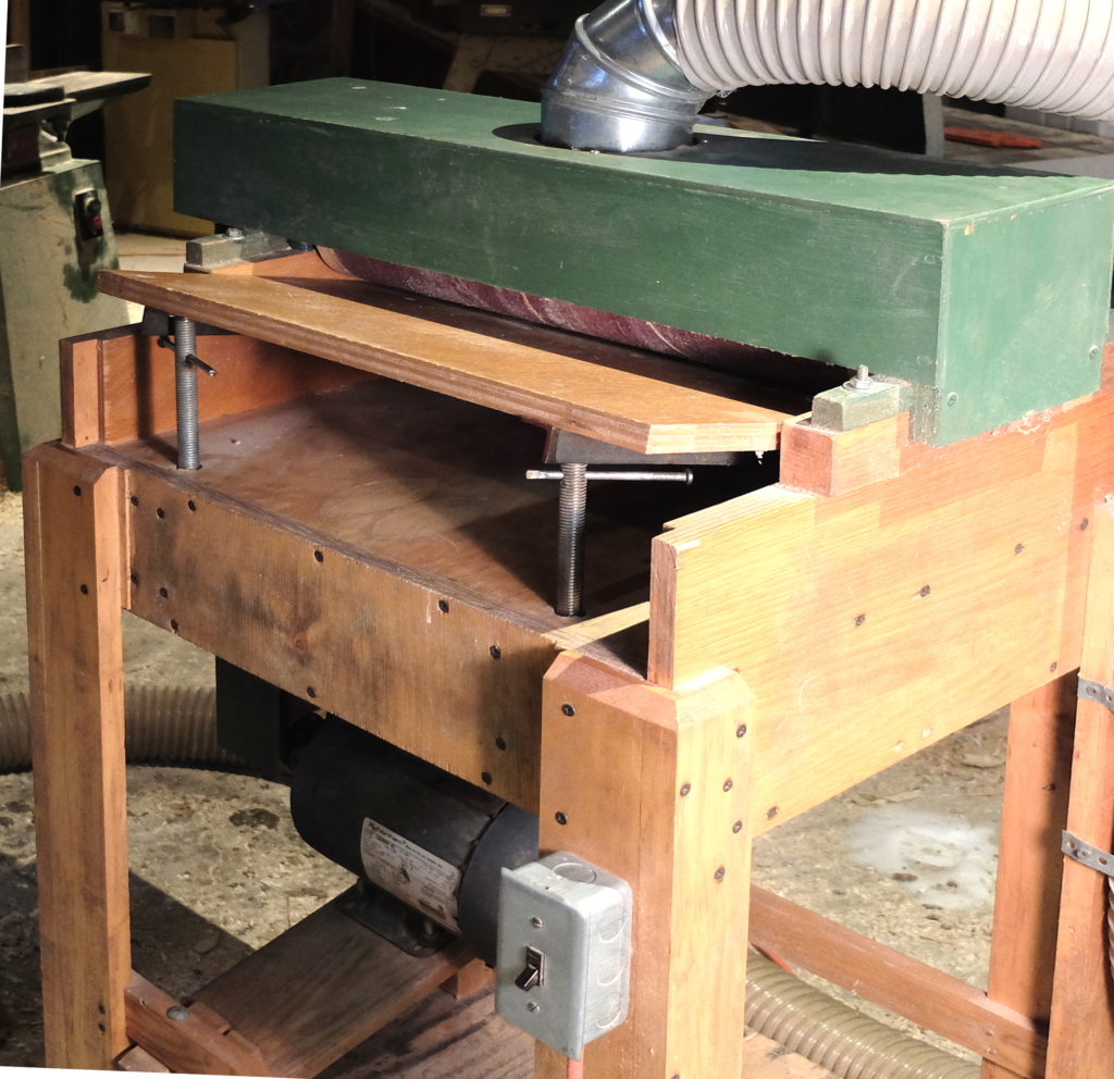
The table beneath the rotating drum has a piano hinge at the back.  Below – view of the sander from the outfeed side, with the dust hood on, showing the piano hinge, the dust hood and the hinged dust flap.

On the infeed side, the table is elevated on two jack screws.  This lets me fine tune the thickness and compensate for any irregularity side-to-side. 

The underside of the table is reinforced with angle-iron so the jack screws rest on steel, and the table underneath the drum is stiffened.

The drum itself is made of 3/4″ softwood plywood discs cut out on a jig on the bandsaw – the jig is just a fixed pin that the disc were rotated around.   The discs were glued together on the 3/4″ steel shaft and pinned to the shaft.  Bearings are self-centering pillow block ball bearings, and the shaft is fixed in place with stop collars.  I assembled the drum and the table and did the final truing of the drum on the machine, using sandpaper on the table to true the drum.

The drum was sized to use standard 6×48″ belts, 4-7/8″ diameter and 18-3/4″ long.  I normally run a 60 grit belt which is glued with contact cement and taped at the ends.   The motor is 1 HP 1,725 RPM with a 2-1/4″ pulley driving a 4″ pulley at the drum, giving about 3,000 RPM drum speed.

The green paint was to suggest a name-brand industrial piece.  The 3M flashing tape on the dust hose is to cover the hole the mouse chewed.

Mini Guitar / Guitalele

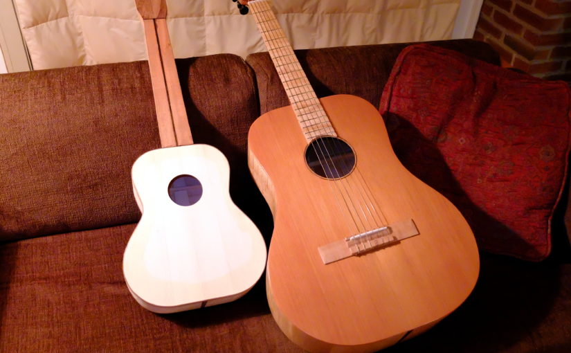
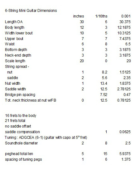
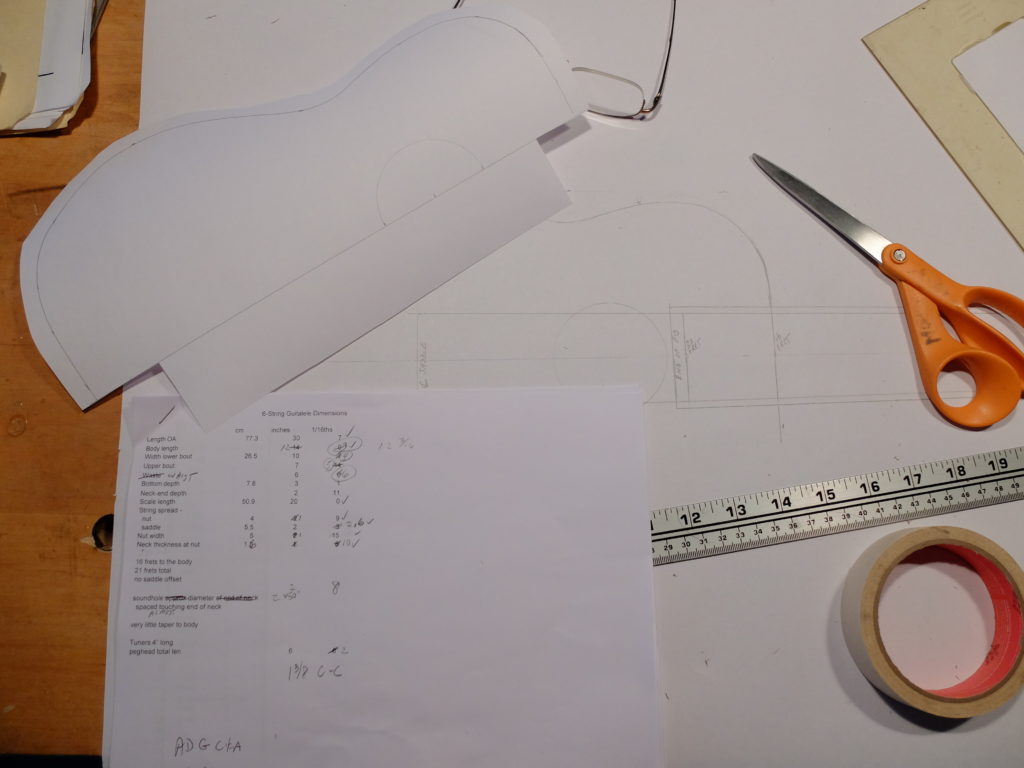
I started thinking about these when I first heard of them last winter and decided to build one after I received an inquiry from a prospective customer.  I developed the plans based on similar instruments to be seen on the internet.   Below is the table of dimensions I worked up to draw the plans.  The plans were drawn out full size and I made a form for holding the sides. 

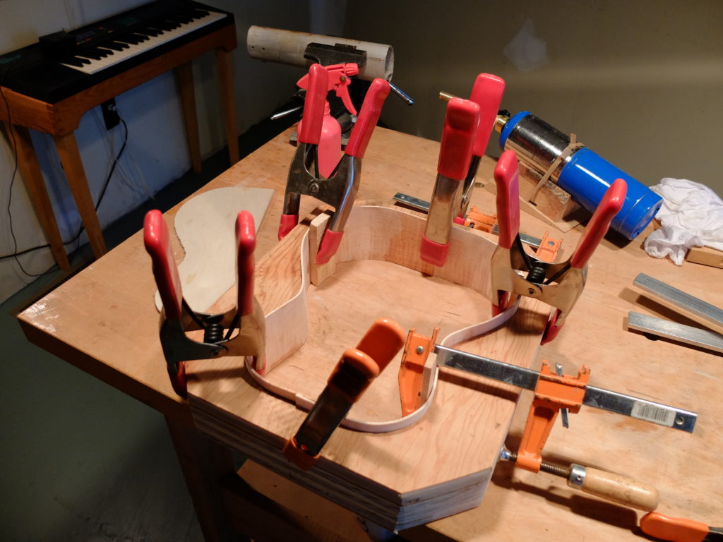
The sides and back are Vermont curly hard maple, about 0.075″ thick.  The sides were hand bent on a short section of aluminum sailboat mast heated by a propane torch.  I prefer bending the sides by hand rather than using a side-bending machine, for both the aesthetics of handling the wood and the control I have over the bend.  The maple bends quite well with lots of heat and a little water.

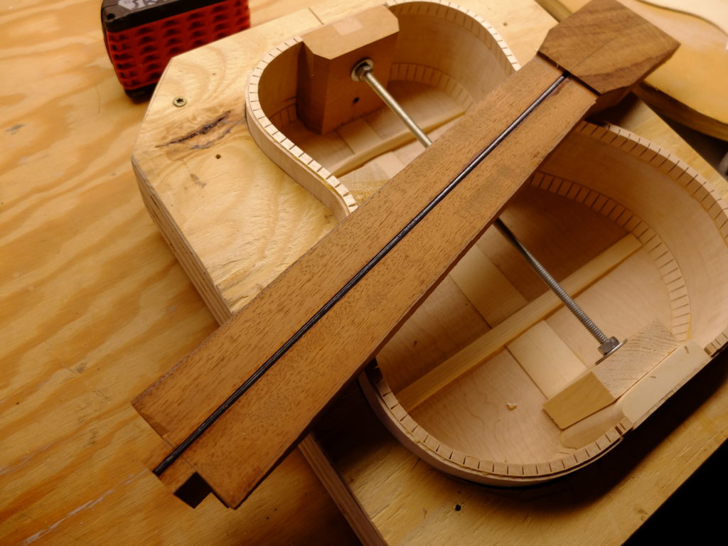
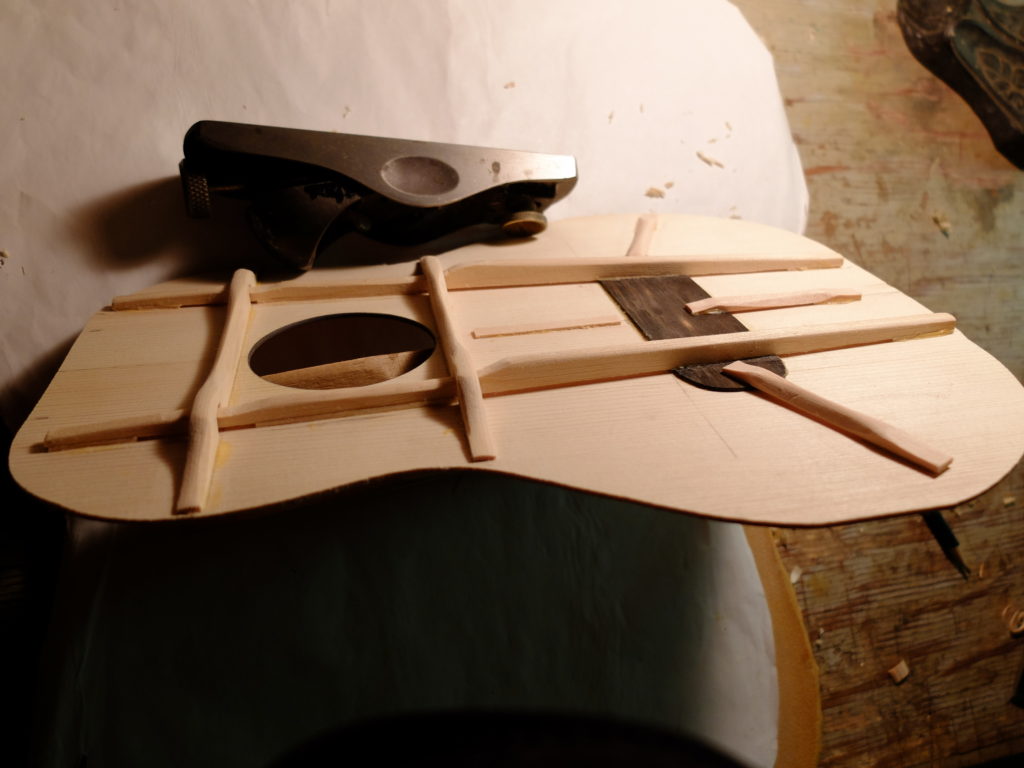
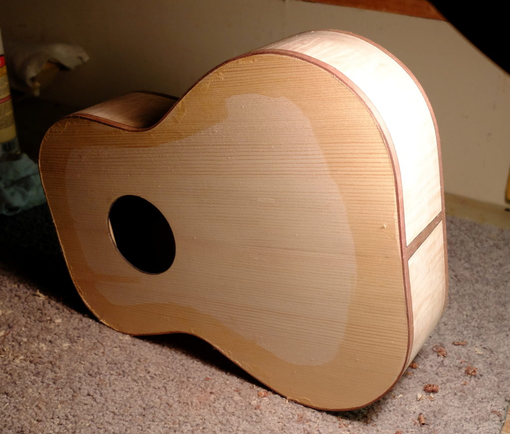
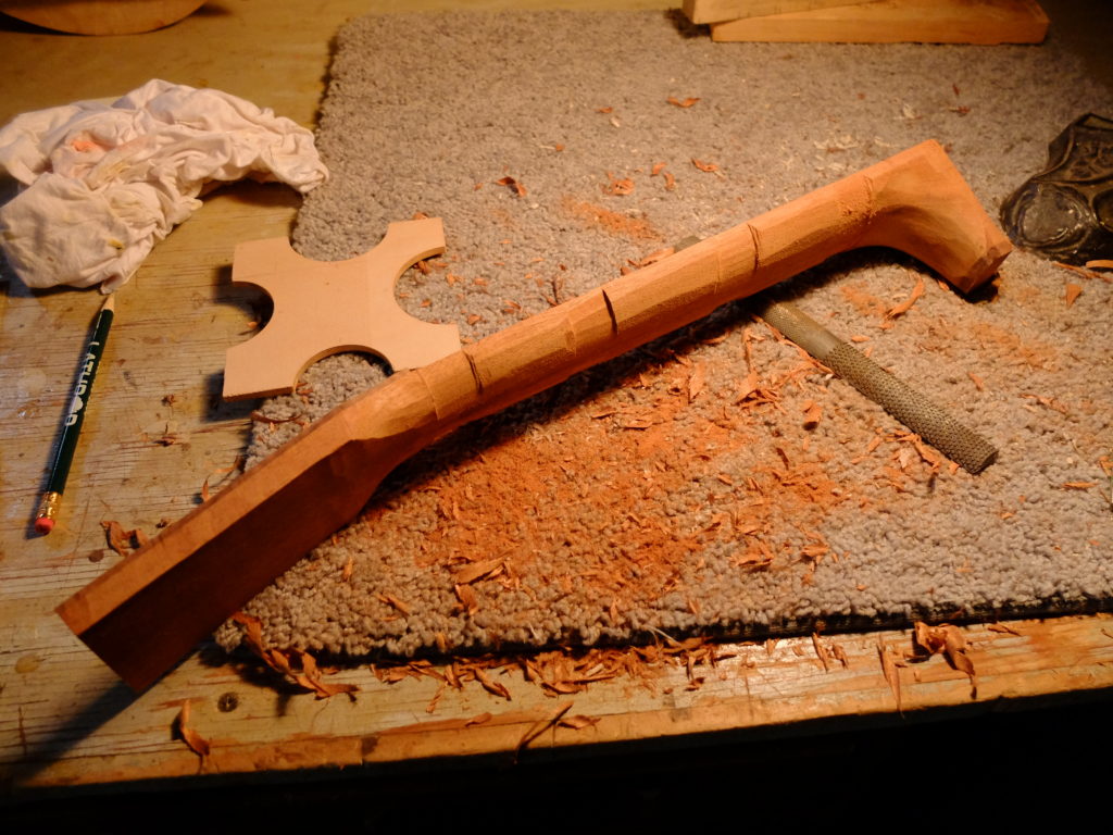
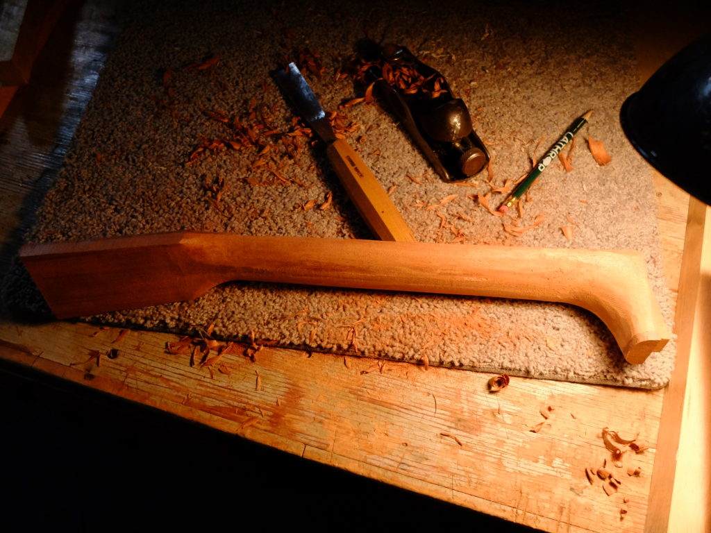
The neck blank came from a single piece of mahogany salvaged from a sailboat bowsprit, and is reinforced with a 1/8″ x 3/8″ carbon fiber rod.  Below – the sides in the form with the back attached, showing the neck blank with koa peghead veneer and carbon fiber truss rod.  I used a straight mortise and tenon bolt-on joint for the neck, using hanger bolts set in the heel of the neck to make the unlikely need for a neck reset easier.  Mahogany neck block, spruce on the heel.The top is European spruce from a violin set finished to about 0.073″ thick.  Since I planned on using a pinned guitar-style bridge, I put in a thin ebony (0.050″) bridge plate to take the ball-ends of the strings.  My bracing was intended to provide resistance to torque on the top exerted by the bridge under tension, while giving some flexibility to the top in the area of the bridge, and uses a sort of elevated reduced-contact approach – the 2 main longitudinal braces contact the bridge but are elevated by about 3/32″ either side of it, contacting the top again at the heel and around the soundhole.  The two cross braces above and below the soundhole do not contact the longitudinal braces, and the small finger braces below and to the sides of the bridge plate are semi-elevated also.  Top glued on, binding on.  The binding is black walnut with a black purfling strip.Two stages of carving the neck – after cutting the fingerboard taper (a little wide of the finished size), I cut the thickness taper and then establish 4 cross sections using a semi-circle template.Then it is fairly easy to join the sectionsQuite a bit later – Strings are D’Addario Folk Nylon EJ34.  I used Tru Oil for the finish, which allowed me to complete this instrument in a much shorter time than would have been possible with a normal oil varnish.
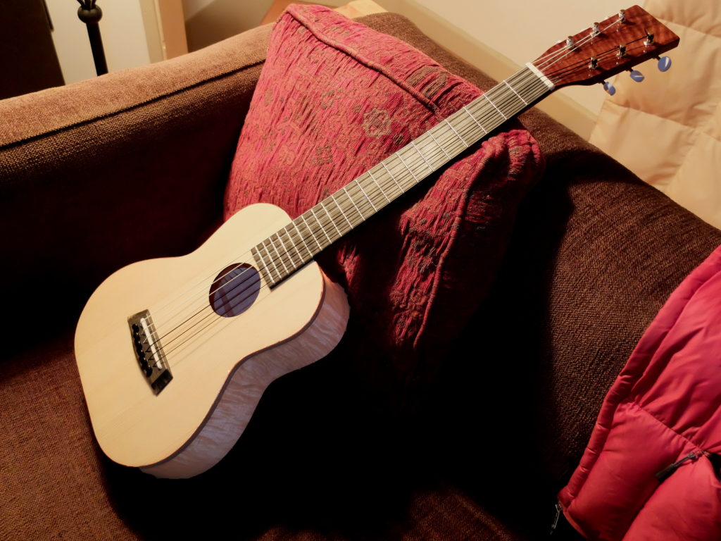
My finishing schedule was :  Lightly wipe down entire instrument with damp cloth to raise the grain.  Let dry and sand to 600 grit.  Apply a sealer coat of dewaxed shellac.  Apply pore filler to any open-grained woods – I used water borne microbead filler from Luthier’s Mercantile.  Sand back filler and shellac with 600 grit.  Start with the Tru Oil.  I used a very old well washed clean T-shirt for applicator pads to minimize lint.  I applied 4 coats at the rate of 2/day and then sanded out the dust nibs with 600 grit.  Apply another 4 coats and sand out to level with 1200 grit.  Apply another 3 light coats, sand back level with 1500 grit, and apply another 2-3 coats.  Sand back level with 1500 grit.  Let it cure for a day or two.  Rub out with Meguiars Medium Cut compound followed by Fine Cut compound.  You will see witness lines that will disappear when you take it to the buffing machine and buff with something like Menzerna Wax 16.  Below – ‘The Witty Irishman’ played by Chris LaPointe recorded directly into a Zoom H4n.

Second Grand Laker

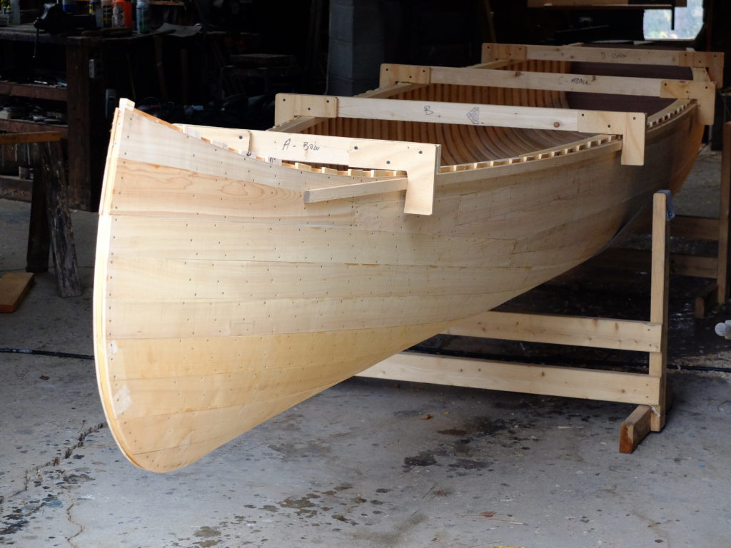
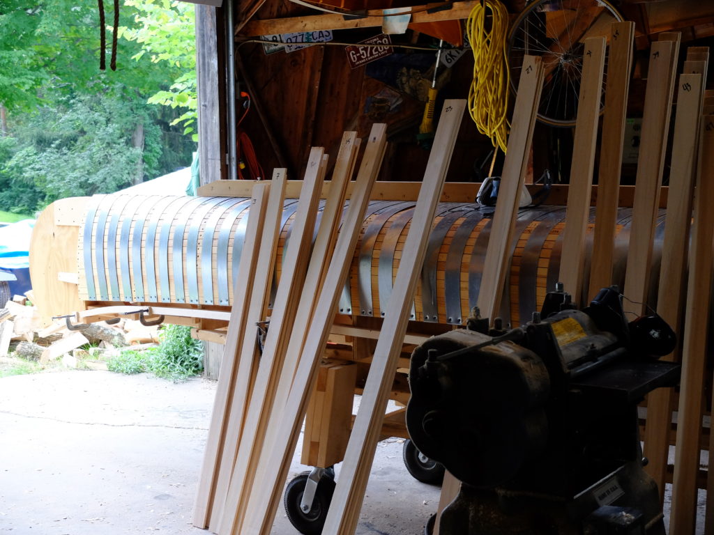
After I got done with crawlspace renovations I wanted to do something fun, and started another (second) grand laker-type canoe.  I had the cedar, I had the form, why not.  It took a while to let the memory of tedium finishing the last one – always the least-fun part – fade enough to want to do it again.  This boat followed the same procedure as the first, with a couple improvements.  First, I have a bigger steamer, a ‘cajun-style outdoor cooker’ rated at something like 50,000 BTU’s which can boil a gallon of water in about 5 minutes.  Much more steam makes bending the 3/8″ ribs easier.  I also soak the ribs for hours before putting them in the steamer.  I was careful removing the planked hull from the form to avoid stressing the inner gunwale – this time, I started unclamping the gunwale at the transom, letting the ribs expand and relax outwards as I continued to unclamp moving towards the bow.  This time, there was no damage to the gunwale.  I also put a 1/2″ x 1″ reinforcing lamination on the inner gunwale after it is off the form as a stiffener.  Finally, I am careful how I store the semi-finished hull to prevent it sagging around the supports before I get the fiberglass on.   First picture – rib stock cut to length but not yet tapered.  There are 54 ribs not counting the 4 pairs of cant ribs.  Ribs measure 2 1/2″ x 3/8″.

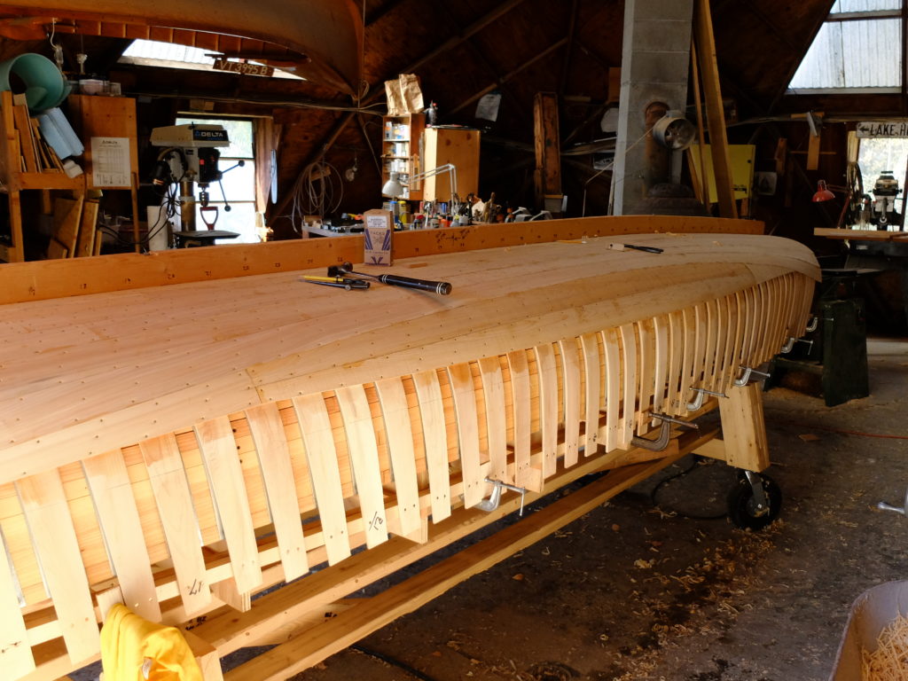
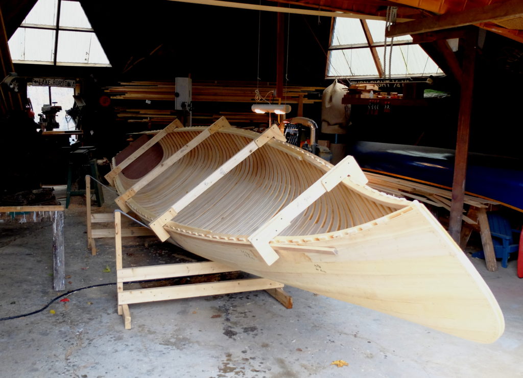
Ribs bent and on, including the 1/2 ribs through the center of the hull, half the planking on (3/16″ x 2 7/8″) – fasteners are 13/16″ brass canoe tacks from DB Gurney Co – part-way through the gored section.

Another view showing next goring plank, and wheels on the ~400 pound form.

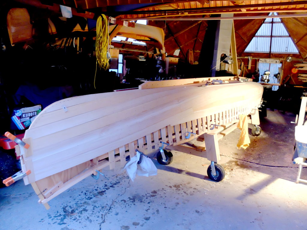
Off the form, sheer strake on, leaving 3/8″ space at top of ribs for the edge of the fiberglass, tied together at the stem and transom.

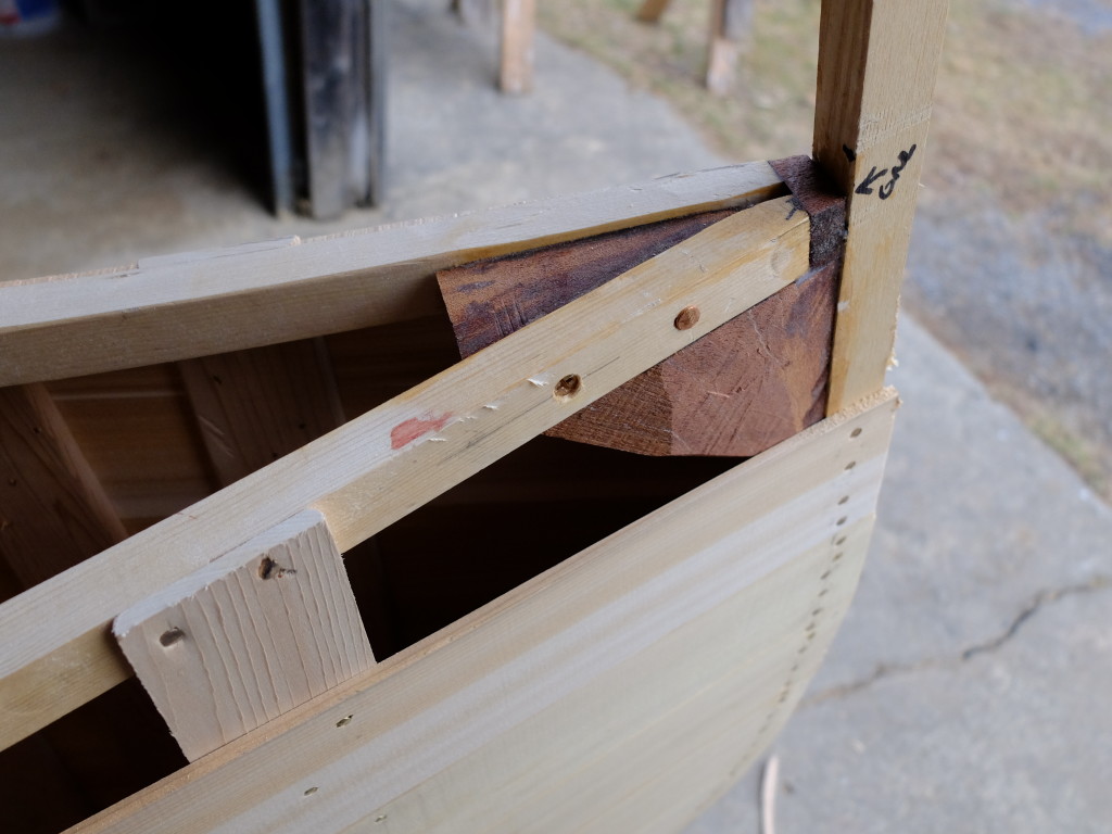
Closeup of my method of tying together the stem and inner gunwale – a chunk of mahogany glued/screwed to the stem and gunwales.  The deck will also attach to it.

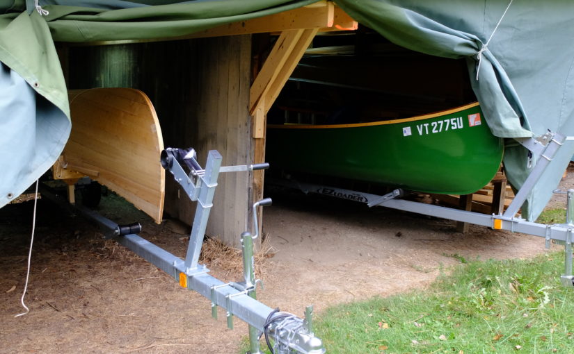
Rolling the semi-finished hull over to put on the trailer for storage – I will finish with the fiberglass work in the spring.  The gunwales are temporarily held in place with the cross-braces and battens.

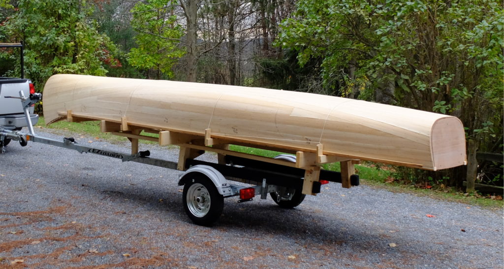
Braced and leveled on a trailer for winter storage.

Concrete steps, a raised bed garden and damp-proofed crawlspace

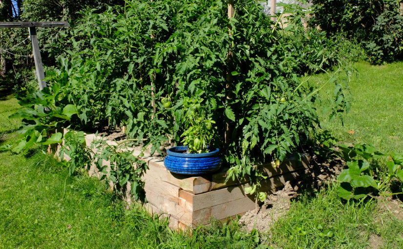
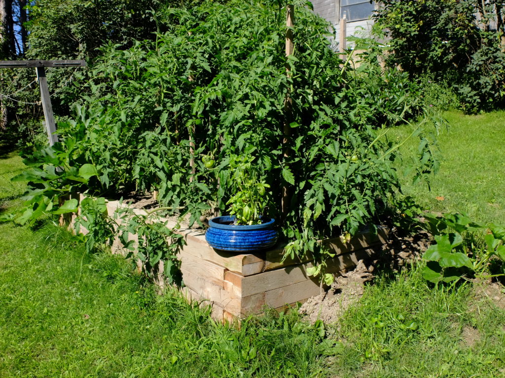
Once I was able to resume work after my hip replacement, the first project was a small raised-bed garden made out of 4×6 white cedar.  Every part of my yard is on a slope, so using the 4×6’s log-cabin style let me build it into the hill easily.  I pegged the timbers together with 1/2″ steel re-bar cut in 24″ lengths and driven in (pre-drilled holes) with a sledge hammer.  The outside dimensions are 10′ x 4′ – the entire space can be reached by hand from the downhill side making weeding etc. a joy.  I got my cedar from the Cedar Sawmill of Swanton Vt, cut to my specs.  My local excavator had some topsoil he delivered and pretty soon we had tomatoes deluxe.  They didn’t stop bearing until we finally had a frost the first week of November.  It also grew 2 pumpkins a bunch of zucchini and some green peppers.  Pretty good for a 3×9′ space.

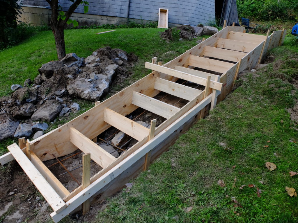
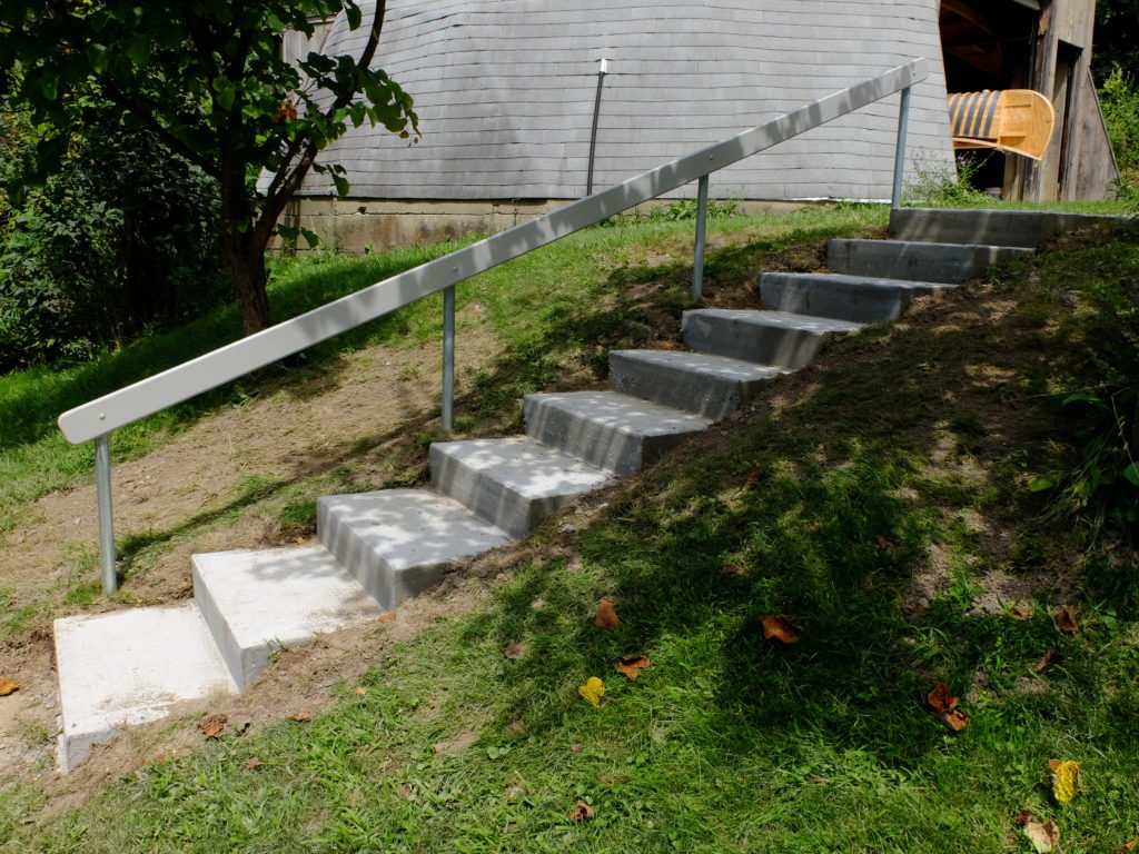
Having entered the age of joint replacements, I also thought I’d better get ready for the next one, which is actually coming up next week.  Hospital discharge planners are always asking ‘do you have outside steps?  A handrail?  Are they uneven?’ – to which I used to answer ‘Yes’ ‘No’ ‘Yes’.  A little perusing the internet suggested that the forms for concrete steps are actually pretty simple – a couple of outside stringers with risers connecting them, and you pour the concrete from the bottom up.  Suggest a ‘3″ to 4″ slump and 3,000 psi’ if you want to sound like you know what you’re doing when you order the concrete.  Calculating the volume is a little tricky – you don’t want to over-buy, but neither do you want to run short.  I took the overall length, made an estimate of the average depth and rounded up a little.  I ordered 2 yards for this pour, and had a little left over.  Removing the old steps was more than half the work – they were made of stones set in mortar that was actually very solid.   That’s a portion of the old steps beside the forms.  I removed material until I would have a minimum of 6″ concrete everywhere.  There is 1/2″ re-bar placed to tie the whole thing together.

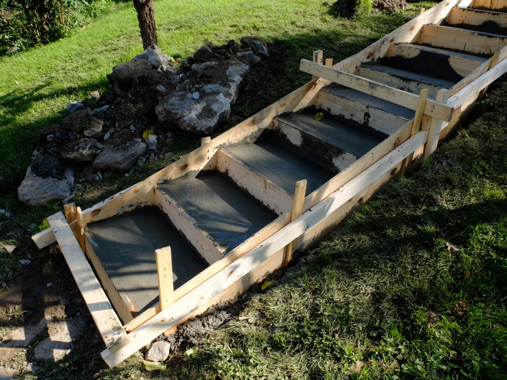
Filled with concrete.  It is good to put a little slope on the steps so they will drain.  I finished the edges with an edger (of all things) and gave the steps a coarse surface with a light brooming. 

The railing is 1 1/2″ galvanized steel pipe (local plumbing shop) set in separate concrete pads, with a white oak railing.  (Boat project is waiting …)

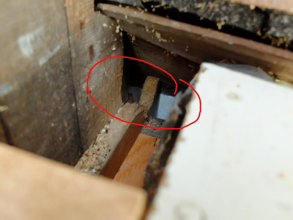
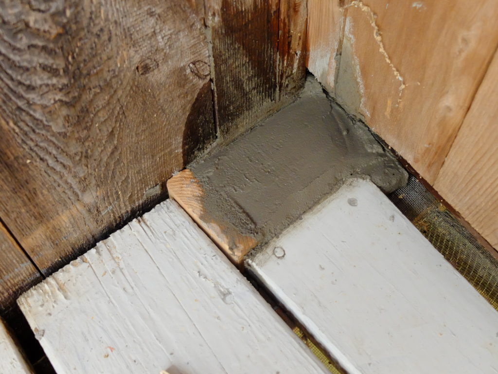
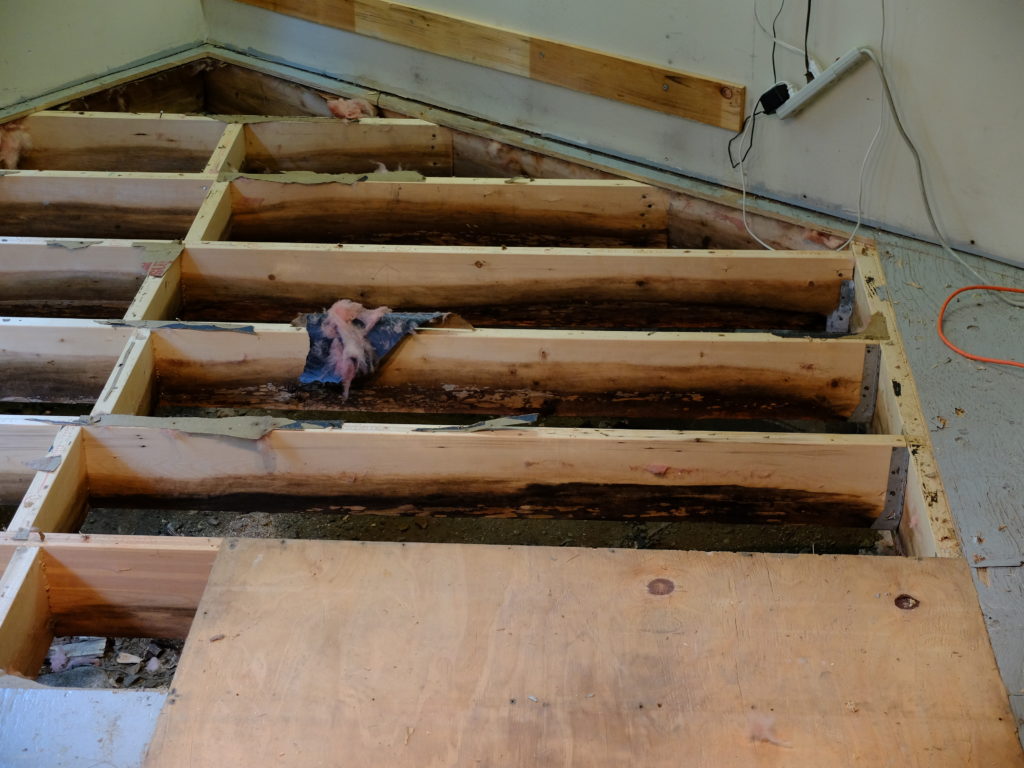
It has been a big mouse year.  Starting with a foray on my screened porch that led to a victory combined with a disaster, things devolved into a protracted battle leading to an uneasy truce.  I found a hole into my rim joist under my front porchand cleverly filled it with concreteonly to discover I not only blocked the point of ingress, but also the point of egress.  The interior mouse population apparently doubled.  (that was the minor victory/disaster).  In pursuit, things got a little out of hand after I decided I’d better check under the basement / guitar shop floor – to find all sorts of rot and corruption – insulation mouse-shredded, wet on the ground (it’s a dirt floor crawlspace under there), joists half rotted. 
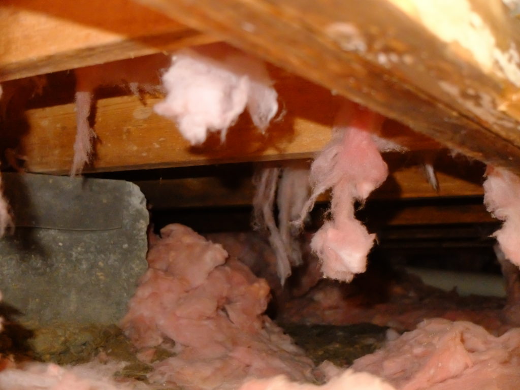
It all had to come out and that’s when I found crawlspacerepair.com

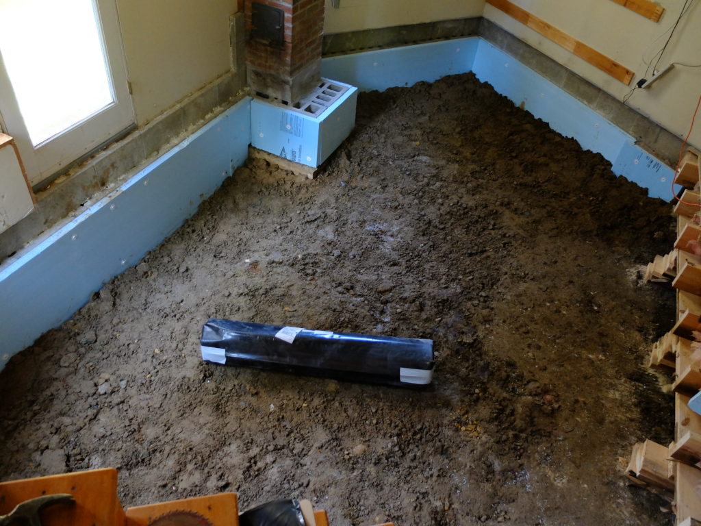
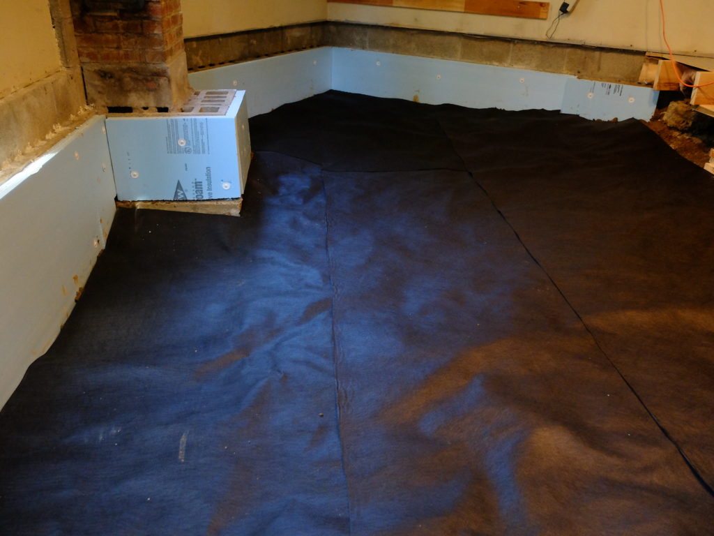
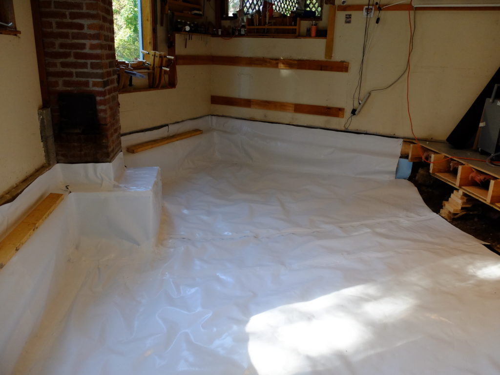
This is not a paid endorsement – I just found their advice and materials and service first-rate.  I took their advice.  I stripped my old floor out, leveled the dirt subfloor so it would all drain in one direction, put down their felt under-layer and sealed the space with their 12 mil Silverback poly, after insulating the exterior block wall.

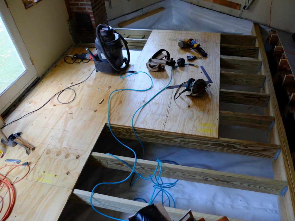
I had to do the floor one side at a time because of all the stuff down there I had no place to move to.  New pressure treated joists, plywood subfloor and pine T&G flooring finished the job.  I did not insulate the new floor, opting to treat the underneath space as ‘conditioned’ space by putting in a couple passive vents in the floor.  If I ever find water accumulating on top of  the poly (I left an access hatch) I will put a little sump pump down there, but so far things are absolutely dry.  I’m very pleased with the result.  Banging down pine tongue and groove with a framing nailer goes against the Fine Housebuilding Code of Ethics – as did my determination to paint the floor – but I already have plenty of nice wood grain to look at, and this is a shop floor, not an art gallery.  I felt good about it.

Another plus – it gave me an opportunity to buy the pneumatic framing nailer I’ve always wanted – a DeWalt DWF83WW.  Great gun.  With this stuff out of the way, I can get back to some fun projects.

Two new guitars

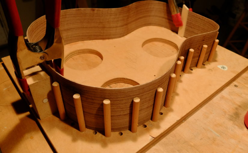
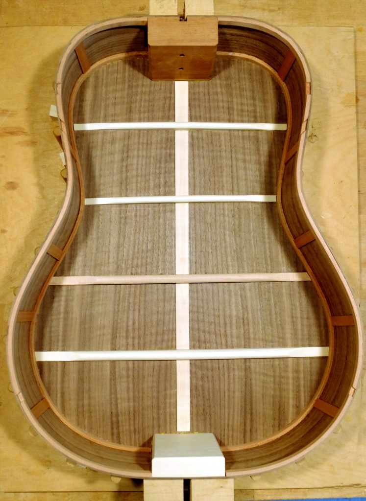
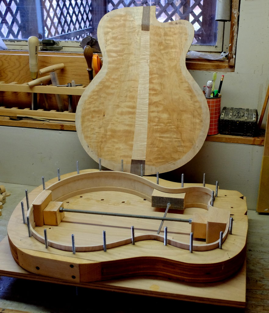
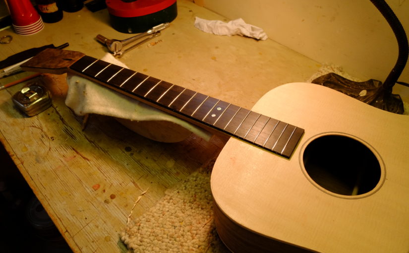
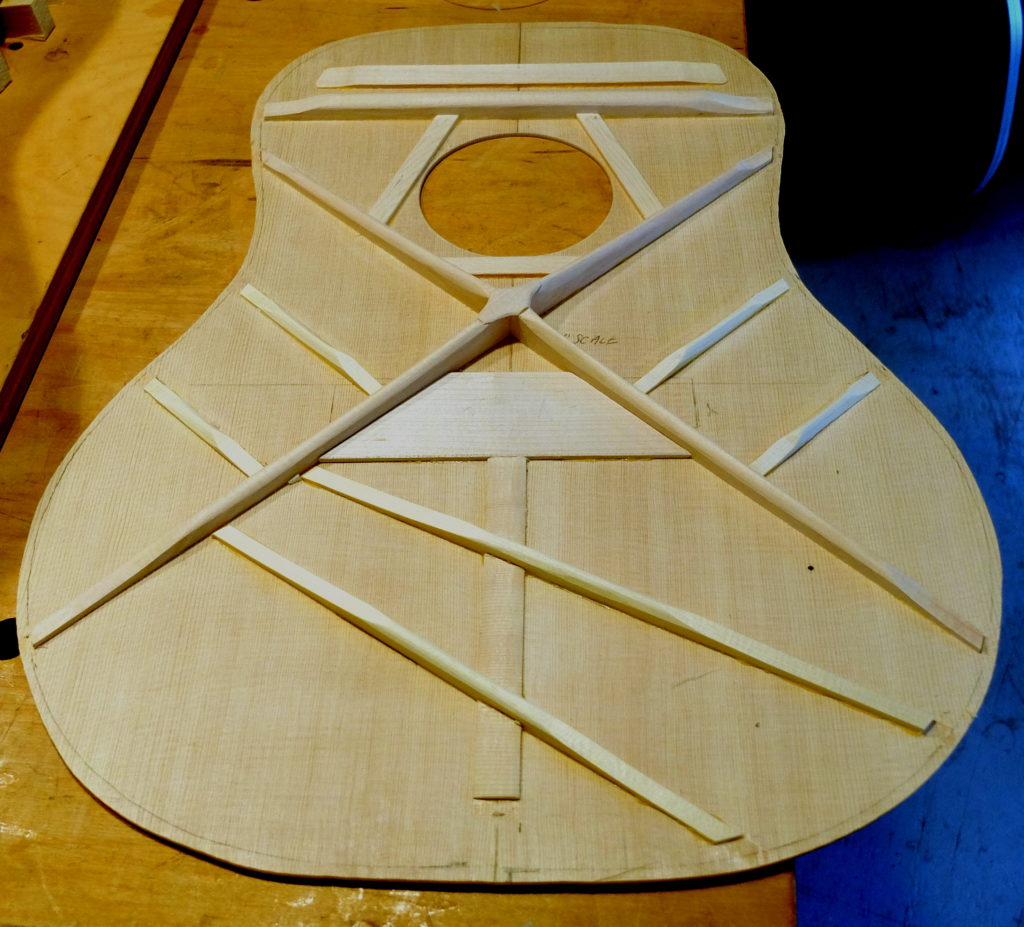
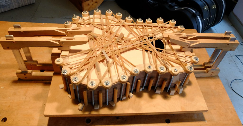
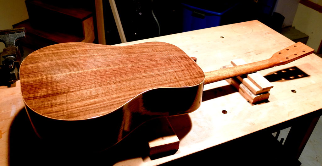
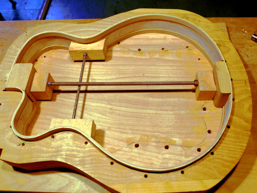
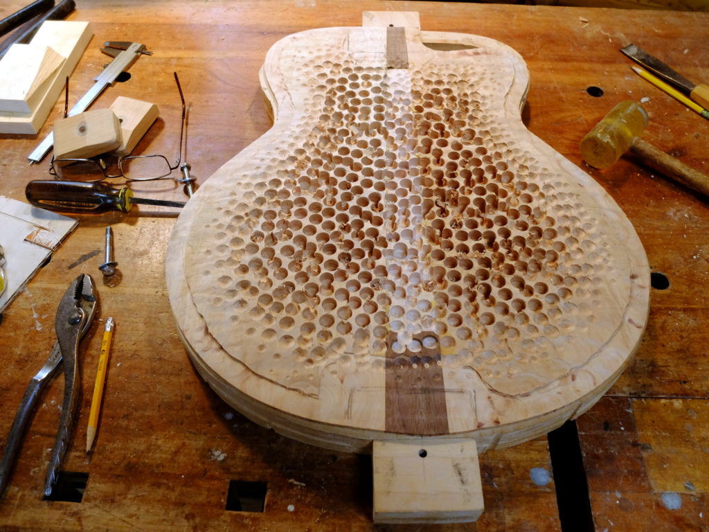
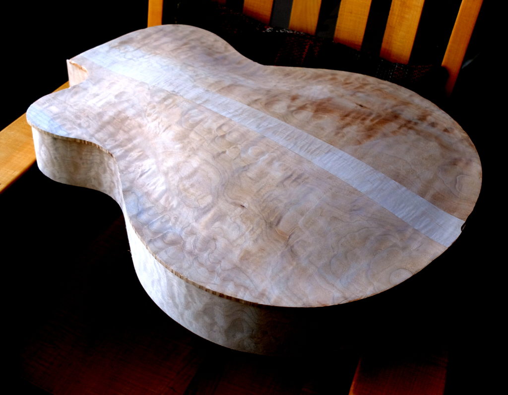
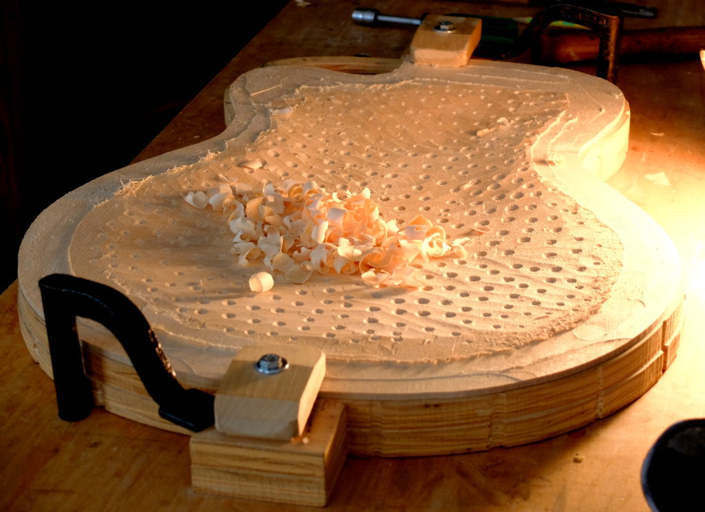
Two new guitars in process – a steel string dreadnought with curly black walnut body and mahogany neck, and a 17″ archtop.  The blog entry about making a fingerboard shows the neck for the dreadnought.  Pictures below – dreadnought back glued up, braced and ready for top to be glued on.  This guitar uses a mortise/tenon bolt-on neck.  I’ve switched to solid linings because I hate cutting kerfed lining.  Solid is quicker and can be a little narrower.  These linings are made of Spanish cedar pre-bent on the bending iron.  Nice curl to the walnut.The top braced and ready to glue – nicely quarted, fine grained Sitka spruce.Gluing up the top – the rubber bands keep the spool clamps from slipping off the edge.First finish coats – de-waxed shellac sealer with oil varnish top coats.  I used curly hard maple for the binding which contrasts nicely with the walnut.This is the archtop – sides bent, solid lining in (these are black cherry), neck and tail blocks in.  The back mid-carving – this is quilted big leaf maple with a curly hard maple center.  Very slow going on the carving because of the hardness and interlocked grain of the maple – over 8 hours.  After putting the outside profile on using templates, the inside is drilled on the drill press to a uniform depth and worked down to a thickness of 3/16″.The back ready to be glued on.Glued on but not trimmed yet.  It’s going to be very pretty.The top mid-stream in carving which is where I left it to get a hip replacement.  I’ll be able to resume work on it in a couple weeks.
Moisture Management in Cabin Structures

My previous blog was about a system for a cabin deck structure.  Observant readers may have noted the absence of any additional vapor barrier.  This  was intentional – and deserves an explanation.

In my part of the country (New England) it used to be standard procedure to incorporate a plastic polyethylene vapor barrier directly behind all interior surfaces, be they walls, floors or ceilings.  This was to prevent moisture moving from an insulated and therefore warmer space (interior) towards the outside colder space and encountering the dew point along the way in the middle of the wall/floor/ceiling and condensing inside that structure.  When condensation occurs inside the building structure all kinds of problems can result, ranging from such things as peeling exterior paint to rot and mold inside and throughout the wall.  With the present emphasis on energy efficiency in buildings, the problem of moisture control has become more complex, and the old standards, like always using a vapor barrier, are no longer taken for granted.  Builders may be constrained by building codes which dictate required structural components, insulation, etc., all primarily intended for year-round residences but overkill and inappropriate in some ways for seasonal cabins.  For example, the design criteria for energy efficiency presents as the ideal a very tight building with all interior air ‘conditioned’ year-round.  If you can build to your own design it will pay to understand moisture management, as the best system for a cabin may actually be less tight and more open.

There is a wealth of published material on this topic, one source being Joseph Lstiburek of Building Science Inc.  The Journal of Light Construction published a practical and thorough book called The JLC Guide to Moisture Control.  Reading these can produce some confusion until certain basic elements are grasped.  The problem is partially that terms have changed – the addition of the new concept of an ‘air barrier’ as distinct from a ‘vapor barrier’ being an example.  The problem is also partly because moisture movement depends on temperature differences between spaces – so one set of procedures applies to Northern climates, whereas a a different structural procedure may apply in Southern climates, all based on the same principles.  So – what are the principles?

The first is that moisture moves from warm spaces towards cooler spaces.  If, along the way, moisture encounters the dew point inside a structure, it will condense.  The second is that you must always provide a path for moisture to move out of a structure once it gets in.  This means ‘no double-sided vapor barriers’.  You have to decide which surface – interior or exterior – you want to be the drying surface.  Thirdly, most moisture moves in the air, with very little by comparison by direct diffusion.  This is where the concept of the air barrier is useful.

One can easily find examples of building systems used in the past that created their own fiasco.  The use of Tyvek house wrap with red cedar clapboards applied directly on top (no air space) is one.  The tannins in the cedar degraded the water resistance of the Tyvek, turning it into a sponge that absorbed moisture, especially on warm days in the sun following a rain – driving the moisture into the sheathing and eventually bringing rot to the entire wall.  There remains value in my mind in tried-and-true methods that a cabin builder can use, and avoid some of the experimentation with new systems and products which may turn out to be their own problems after a few years.  For example, some of the products now in use, like the ZIP system of plywood sheathing with a pre-applied waterproof surface, call for special attention to the ‘no-double-sided vapor barrier’ rule.  I think, done wrong, these will lead to problems.  Understanding the principles will help do them right.

Going back to my floor structure.  The main moisture drive will be from inside the building to the outside.  There are small air spaces between the foam insulation and the subfloor, but most air infiltration into that space will be outside air because the subfloor is glued tongue-and-groove acting as a pretty good air barrier.  During construction the subfloor will get wet and some moisture will make it through the subfloor to the insulation.  The main object then is to allow a way for the floor to dry out.  It will dry to the inside.  Any moisture that gets into the air space from outside will only condense if the floor structure is cooler than the outside air, which is not likely unless the cabin is heavily air conditioned, which is not in the plans for this building.  The poly vapor barrier would only get in the way and was therefore omitted.

Cabin Flooring System

I have built a small number of seasonal cabins and now use a flooring system that has some advantages over other methods.  By ‘floor’ I am referring to the main deck of the cabin which is built on posts without any basement type foundation.  My cabins have been built in places where all materials are carried in to the site by people, meaning the sites are not accessible by cement truck, and neither is it desirable to use excavating equipment because of the clearing that would be needed to get an excavator to the site and give it room to work.  So, first of all, this method allows all work to be done by hand and allows the use of materials which can all be carried in by hand.  The use of a post foundation means that the deck is above but usually close to ground level.  While the underside of the deck / joists could be left open, in most cases it is desirable to use some insulation and that then means that the insulation must be sealed from below to prevent mice and other rodents from getting into the assembly and thence into the cabin.  It is assumed that the cabin will be unoccupied for long periods of time, like most of the winter, and the last thing you want is rodents getting in and making a mess.  It is also worth thinking about the space under the deck and how to keep larger animals like opossums from making themselves to home – the best solution being to be to keep the sides of the deck clear, omit any kind of skirting, and checking every now and again for signs of anything trying to den up down there.

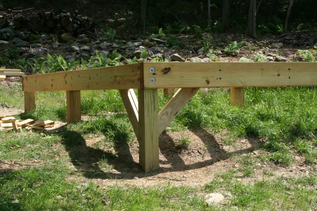
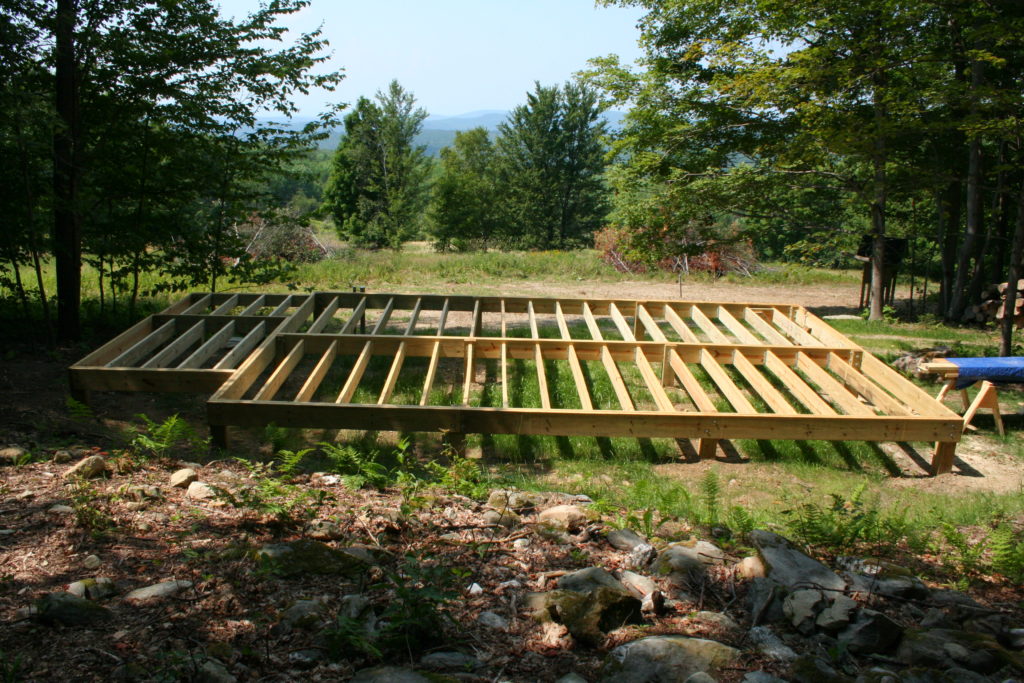
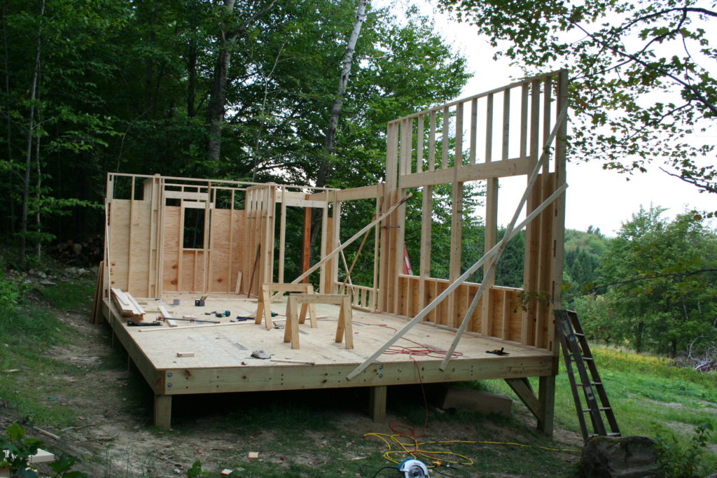
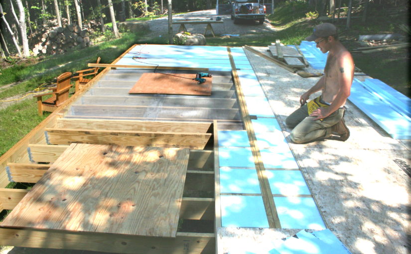
The foundation consists of posts which can be wooden PT set on a concrete pad below whatever you consider frost level, or you can use concrete posts poured in sona tube.  In this case, a cabin my son Luke and I built in Vermont, we used 6×6 PT posts set 4′ deep, each one resting on a bag of sacrete.  The peripheral beams are double 2×10 PT let into the posts and lagged to eachother.  Posts are every 8 feet.  The main deck is 16′ x 24′, and there is a central carrier beam so we could use 8′ joists.   Below – posts in and peripheral beams ready for joists.

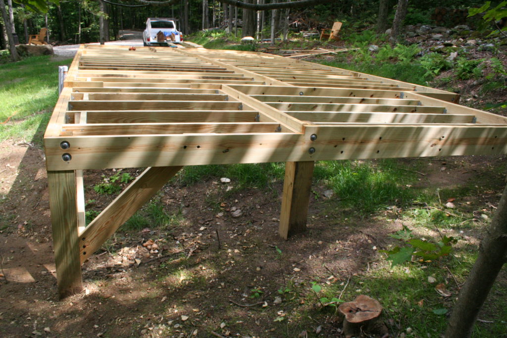
The 2×8 joists are set in joist hangers 2″ below the top of the peripheral beam to leave room for foam insulation.

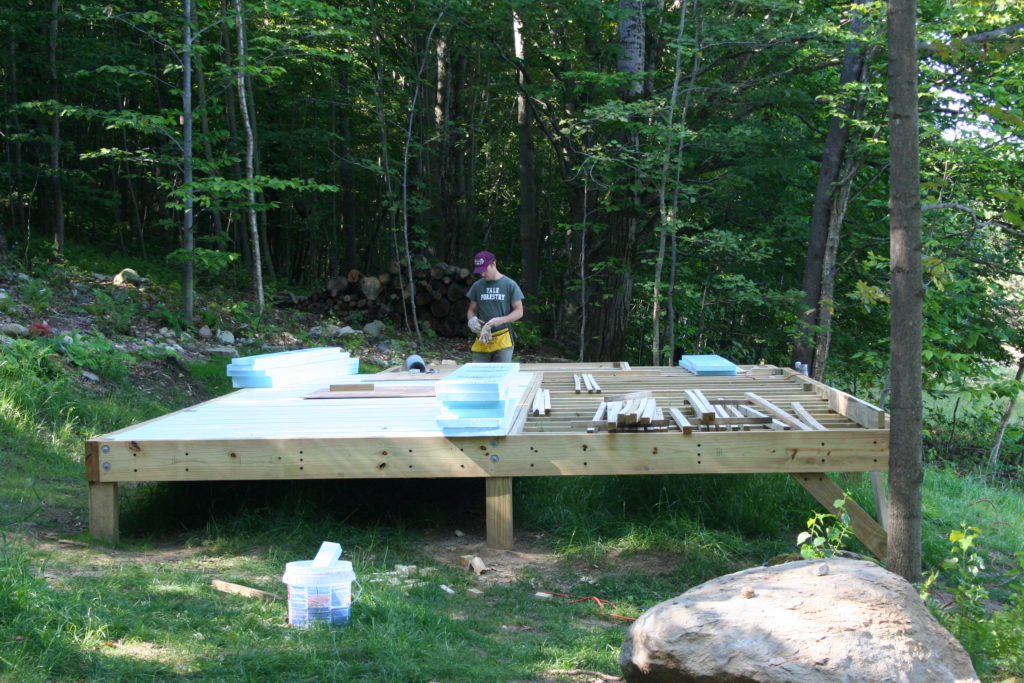
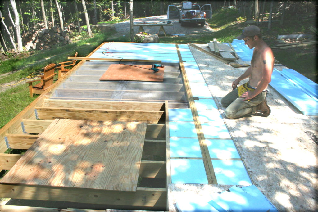
A layer of 1/4″ mesh hardware cloth is carefully laid directly on top of the joints – this is the rodent block, and then 2″ blue-board foam insulation is fitted into all the spaces between joists.  Sleepers 2″ tall are nailed to the top of the joists, bringing everything up to the level of the peripheral beams, and then the Advantech subfloor goes on.  Pressure treated lumber is used for all structures below the subfloor.

And then you can start framing.


Making a Fingerboard

Yes, you can buy pre-slotted, pre-radiused, pre-fretted fingerboards – but making your own gives you the freedom to select scale length, radius, fret size etc.  I make many different sizes and types of instruments and use the same method for making the fingerboards for all of them.  So – here is my method of making a fingerboard.

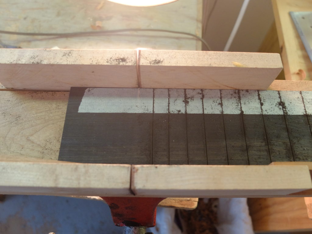
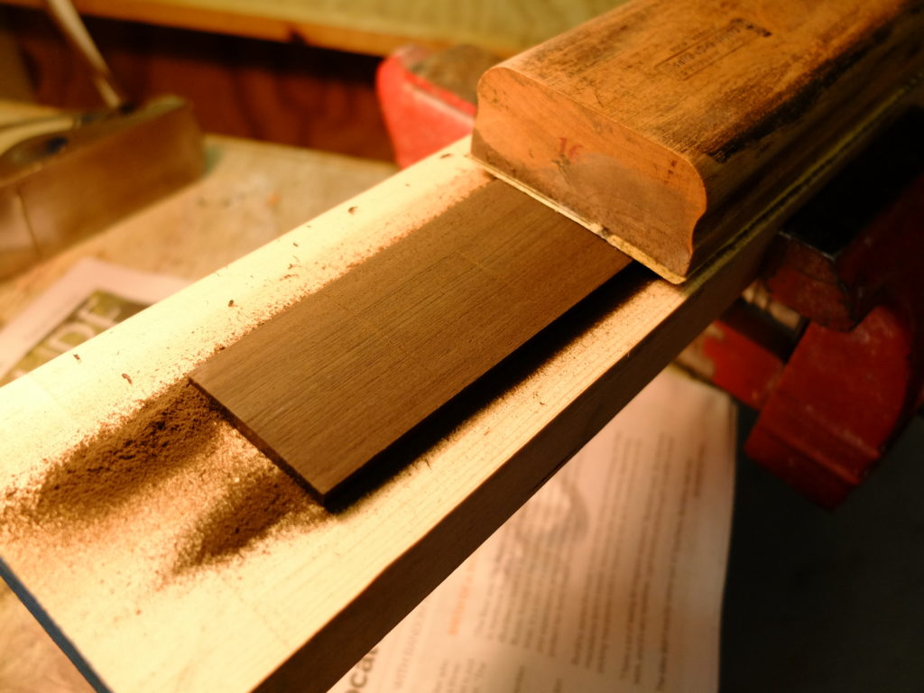
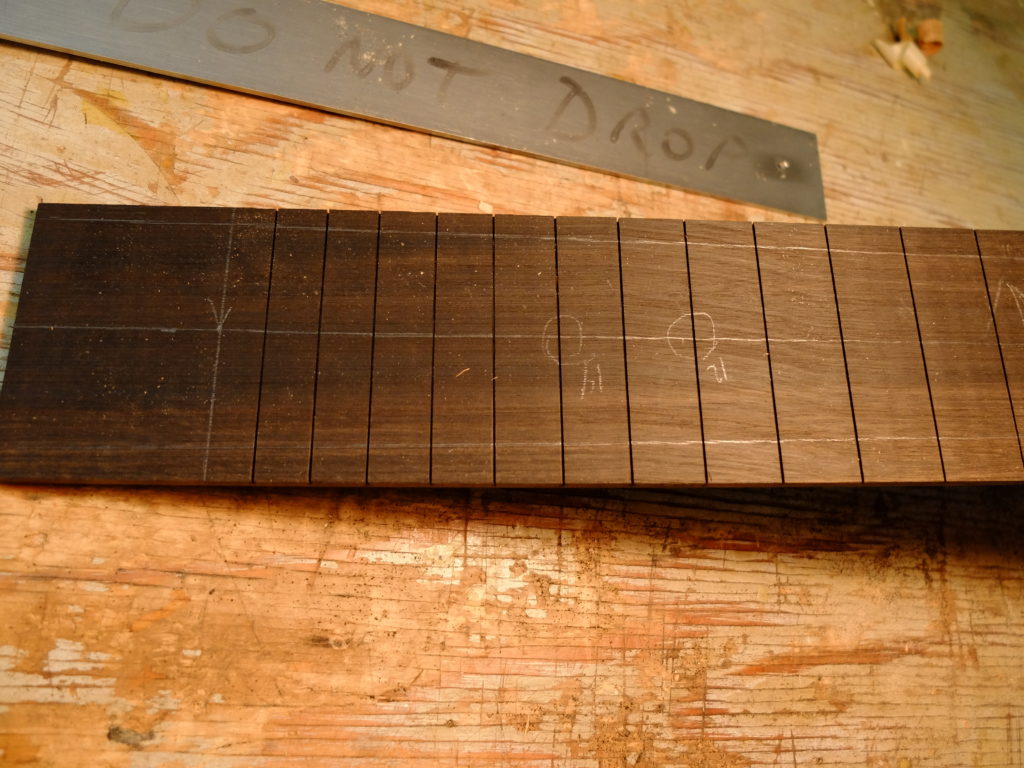
Starting on the jointer with a fingerboard blank – this one is second grade ebony –  I straighten one edge and flatten one face.   Then I use the thickness sander to reduce the thickness to somewhere around 0.200″.  Steel string necks are finished to a total thickness of 0.850″ at the first fret, going to 0.950″ at the 12th, so a 0.200″ fingerboard leaves me 0.650″ of neck material at the first fret, which is just right for a truss rod slot that is 0.440″ deep.  I leave a little more material under the truss rod end beneath the nut for good measure.  I put a piece of masking tape along the true edge of the blank and mark the fret positions accurately with small pencil marks.  I use a fret scale ruler from Steward MacDonald to locate the frets for ‘normal’ scales, or measurements from the fret location calculator that Stew-Mac offers for scales that aren’t on the fret ruler, like bass and uke scales.  (This may sound like a plug for Stew-Mac, but it isn’t.  I just happen to use some of their tools).  Next, the blank goes into a homemade miter box, true edge towards the back fence.  A light placed behind the box shows through the slot to line up the fret location marks.  If I don’t move the light, each mark will come out true relative to the others.

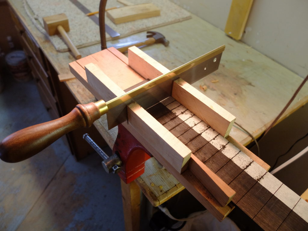
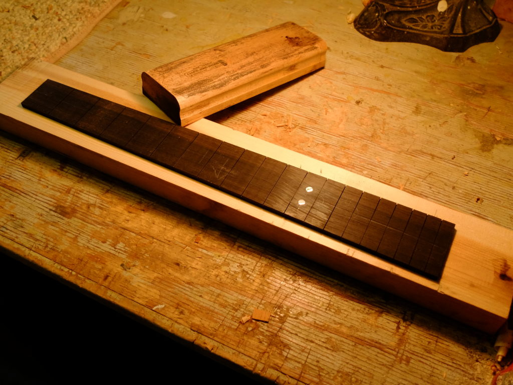
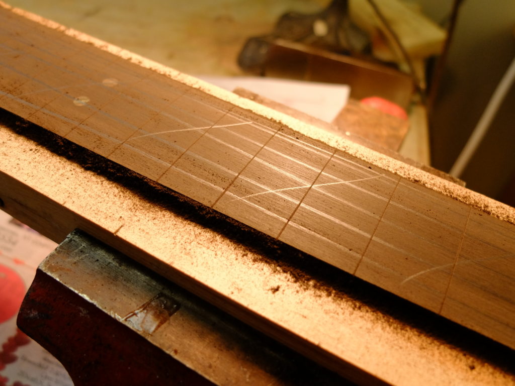
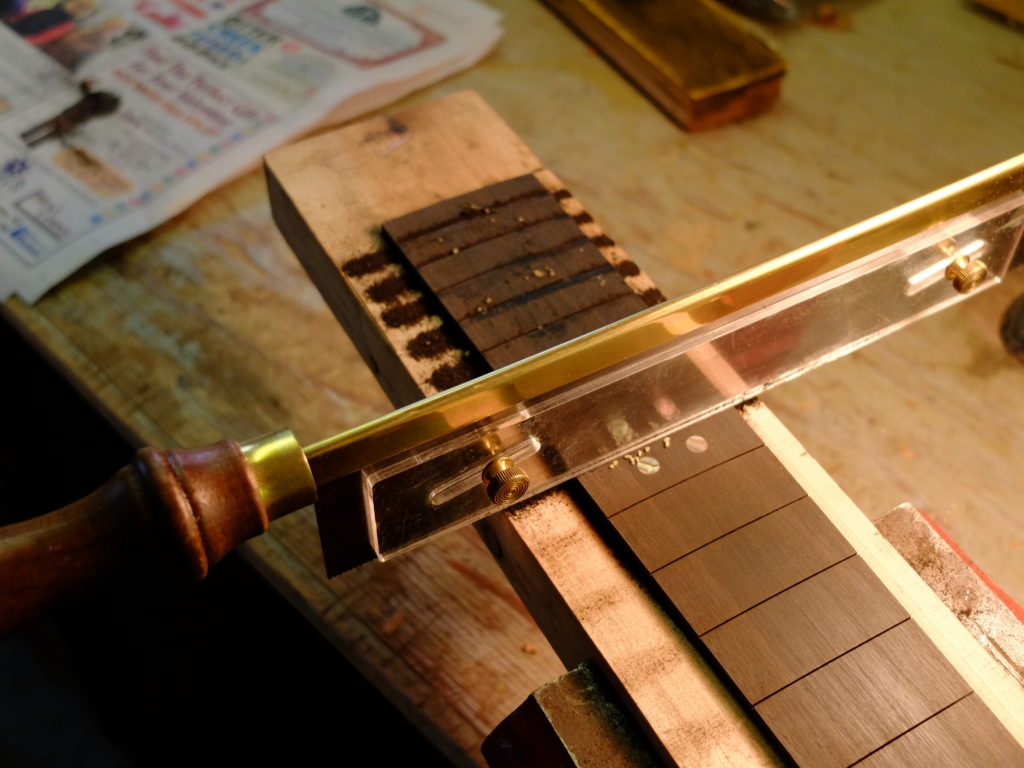
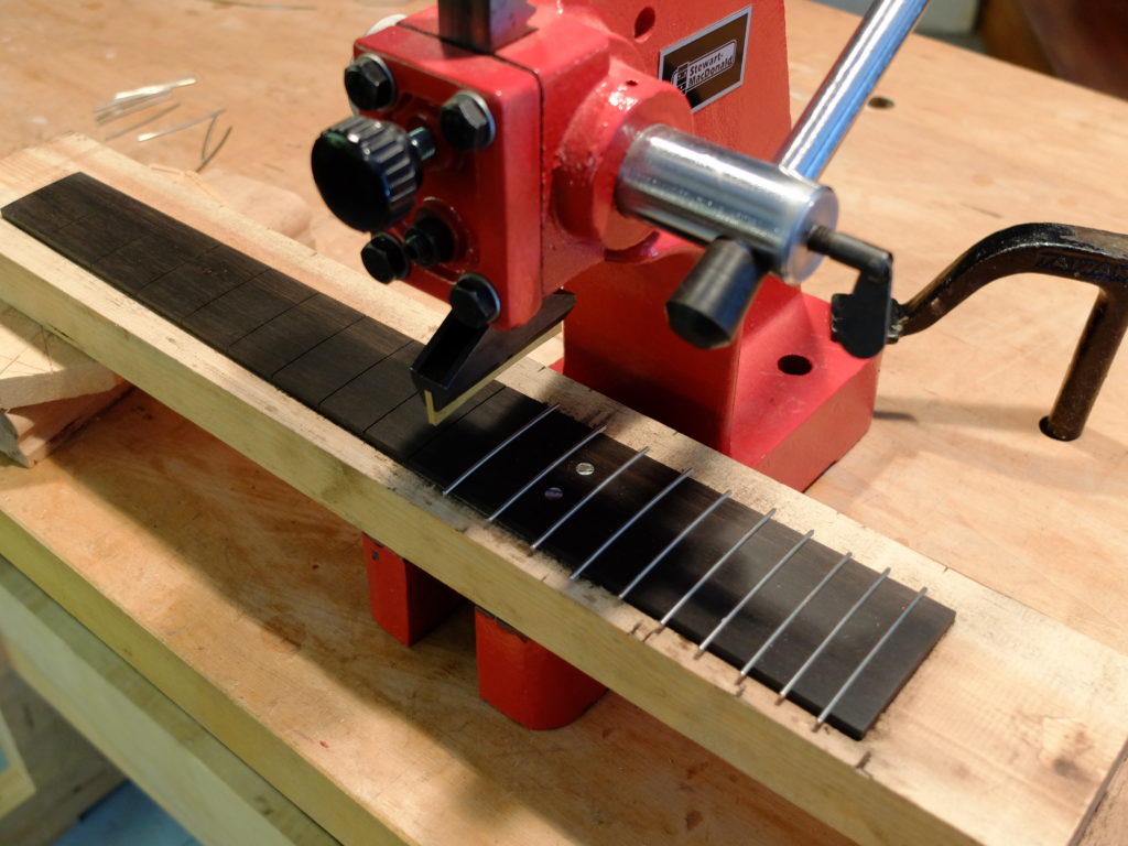
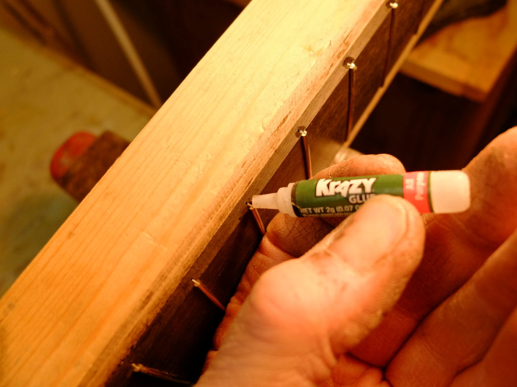
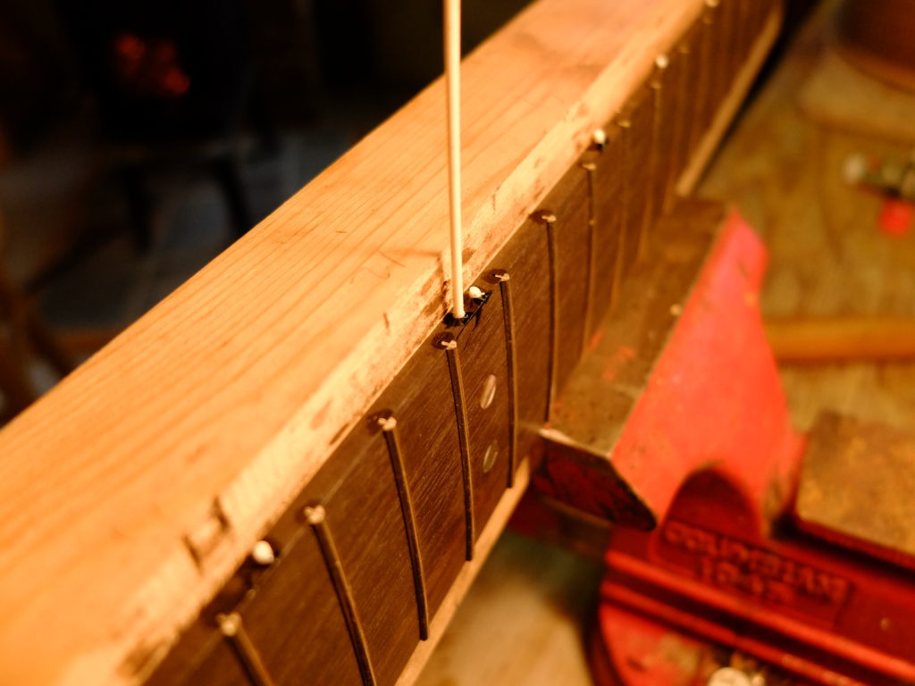
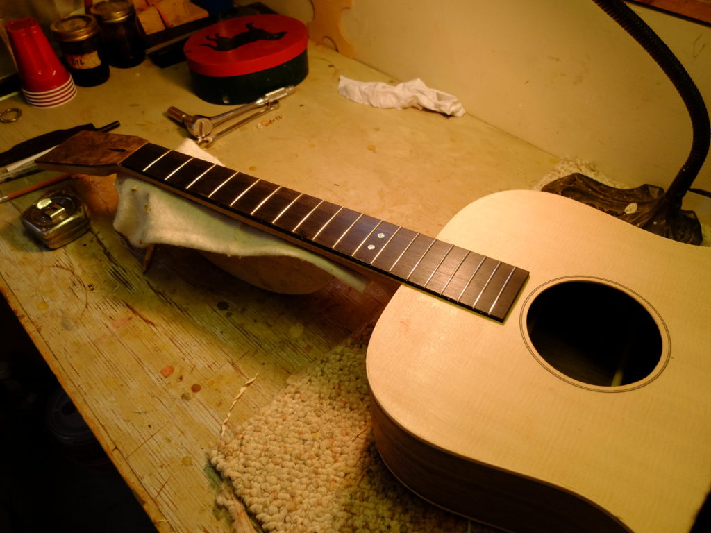
The purpose of this phase is to get all the slots started, at right angles to the edge, but not take them to their finished depth – that comes after the radius is put on.  I am using the Stew Mac pull-stroke fret saw.I use wedges to hold the board in place for each cut.  After all the slots are started, I mark the taper – 1 11/16″ at the nut to 2 3/16″ at the 14th fret – and then cut that out on the bandsaw and clean up the edges with the jointer after cutting the board to its finished length. Now is the time to do any inlay – this one has abalone dots at the octave position.  I lightly glue (2 small drops of Titebond) the board to a flat, rigid backer, and start in with the radius sanding block with 80 grit paper.  This is a flat top and uses a 16″ radius.  I use rubber cement to glue the paper to the block.The radius goes on fairly quickly – I make a series of pencil marks on the face, and when they are all gone, I can stop with that grit.When I have the whole board radiused, I stop and cut all the slots to their finished depth with the Stew Mac pull-stroke fret saw with depth attachment.  I use a lubricant called Pro Cut to help keep the saw from binding.  I shoot for cutting the slots at least 0.010″ deeper than the fret tang.Now that I have the board radiused at 80 grit and the slots at their finished depth, I take the radius sanding block and work up through 120, 220, 400 and 600 grit successively, ending with a 0000 steel wool polish.  This results in a semi-mirror finish ready for frets.  I happen to use the Stew Mac fret press.  You have to carefully line up the press caul with the fret to avoid tilting it, but pressed frets generally give a more uniform fretting job than hammered frets.After all the frets are in, they are snipped close to the edge and then a drop of Krazy Glue is applied to each fret end.Next, I drill and put in the side dot markers – these are 1/16″, glued in with Krazy Glue.Then the board is removed from the backer with a warm seam-separation knife (Stew Mac has one, if you don’t already), the ends of the frets are filed flush with the edge of the board and I’m ready to glue the board to the neck.

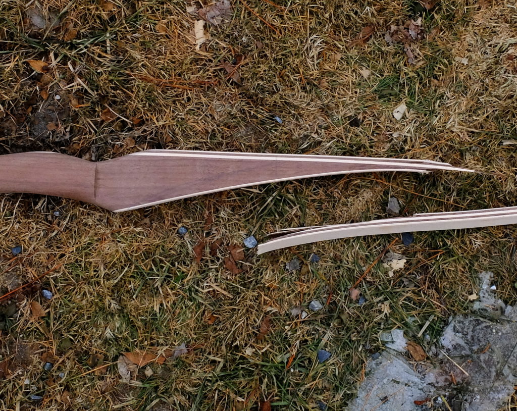
Reflex Deflex Longbow

I decided to try to build a couple bows.  The first one worked out, but only pulled 25 pounds, which is nice and easy for target practice but I wanted a heavier bow.  The first, and numbers 2-4, were made without fiberglass outer (back and belly) laminations, and would not hold together when I tried for a heavier draw – 2, 3 and 4 broke when drawn.

Per usual for me, I switched to standard methods and had success.  I added fiberglass belly and back laminations.  That step made the core woods secondary as strength members.  I used directions from a YouTube by Dave Watson, who also published a plan for the bow he describes in the video.

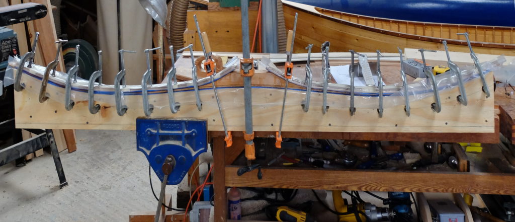
I made several modifications to his design.  First, I built mine as ‘reverse handle’ by inverting the form, or, rather, making the ‘female’ component of what could be called the ‘male’ version of the form he shows.  I used C-clamps instead of his rope-and-wedge system, and I used System 3 Silvertip epoxy instead of the Smooth-on.  I was able to omit the hot box because the Silvertip sets up fine, albeit slowly, without extra heat.  I followed the lamination schedule in his plans  using black cherry for the core woods.  The Bow-Tuff that I got from my local boyer, Jim Duclos, was nominal 0.050″ thick instead of the 0.030″ that Dave specifies.  This made a huge difference in the finished draw weight.  Using his specified taper of 1 1/2″ at the fades to 5/8″ at the nocks, I could not draw it to get a string on it – it probably was pulling around 70 pounds, whereas his design with the 0.030″ Bo-Tuff drew 38 pounds.  I was able to get the bow down to 35 pounds by reducing the width at the fades to 1 1/16″, going to 9/16″ at the nocks.

This is the bow in my form being glued up.  It is winter time here now, and on a warm day I can get the shop up to 60 degrees, but it still drops to freezing overnight.  I moved the form inside after the epoxy was set up enough to stop off-gassing, and left the clamps on for a total of 48 hours.

There are recesses cut in the form for the heads of the clamps.  A double layer of 1/8″ hardwood, wrapped in poly, is used to spread out the clamp pressure.  There was no discernible variation in limb thickness between clamps compared to directly under the clamps.  The point where the back laminations meet the fades for the handle takes special care to prevent voids.

I used a bandsaw with a wood-cutting blade to cut the limb tapers.  That destroyed the blade.  On my second go at tapering the limbs (trimming down the original 1 1/2″ width) I used an oscillating spindle sander to approximate the line and then cleaned it up on a stationary belt sander.  This saved me the cost of another blade.  I’ve ordered a bi-metal 10/14 wavy tooth metal cutting blade for  my next try.  A big advantage of using a bandsaw to cut the fiberglass is the ability to control the dust.

There are differing opinions on how to adjust draw weight.  Two experienced boyers advised that Bo-Tuff could be sanded to reduce weight – 0.001″ of thickness corresponding roughly to 1 pound reduction.  Jim Duclos advised using 120 grit and a hand sanding block and watching carefully as the weight will come off quicker than expected.

Getting a string was an unexpected problem.  My bow, which measured 68″ nock-to-nock needed a 66″ string, actual length.

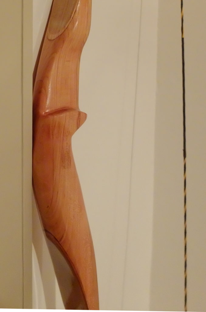
Bo-Tuff is not uniformly thicknessed, hence my ‘nominal’ 0.050″ mentioned above.  The next bow I make will use Bo-Tuff from OMC Boyer Supply which they regrind to actual thickness, and I will use 0.030″ and see if I can hit the 38 pound bow Dave Watson designed.  Below is the handle of the bow I built.